Maintenance Section
-117-
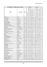
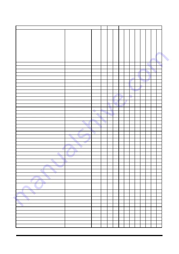
Quick Reference to Maintenance Schedule
FIRST EVERY
ITEMS SERVICES
PAGE
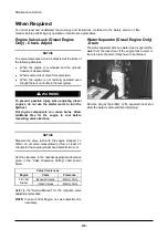
W
hen R
equi
re
d
50
-1
00
S
e
rv
ic
e H
our
s
or
a
W
eek
250 S
e
rv
ic
e H
our
s
o
r a M
ont
h
10
S
e
rv
ic
e H
our
s
or
a
D
a
y
250 S
e
rv
ic
e H
our
s
o
r a M
ont
h
500 S
e
rv
ic
e H
our
s
o
r 3 M
ont
hs
10
00
S
e
rv
ic
e H
ou
rs
or
6
M
ont
hs
15
00
S
e
rv
ic
e H
ou
rs
or
9
M
ont
hs
20
00
S
e
rv
ic
e H
ou
rs
or
a
Y
ear
25
00
S
e
rv
ic
e H
ou
rs
or
15 M
ont
hs
45
00
S
e
rv
ic
e H
ou
rs
or
2
Y
ear
s
Air Breather
Change
152
O
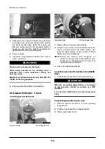
Air Cleaner Indicator
Check
126
O
Air Intake System
Check, Clean
136
O
Air Intake System
Change
151
O
Battery Terminal
Clean, Inspect
142
O
Belts(Diesel E/G Only)
Check, Adjust
144
O
Carburetor(LP-Gas E/G Only)
Adjust, Clean
150
O
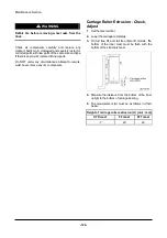
Carriage Roller Extrusion
Adjust, Check
124
O
Carriage Side Rollers
Lubricate
141
O
Carriage Sideshifter(If Equipped)
Lubricate
146
O
Circulation Pump Belt(OCDB & LP-Gas E/G Only)
Check, Adjust
147
O
Cooling System
Clean, Change
161
O
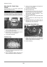
Drive Axle Oil
Check, Clean, Change
142
O
Drive Axle Oil & Strainer(OCDB Only)
Check, Clean, Change
147
O
Drive Axle Oil(Shoe Brake Only)
Check, Clean, Change
156
O
Engine Oil & Filter
Change
142, 148
O O
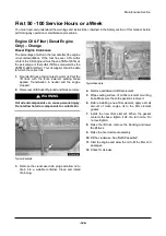
Engine Oil & Oil Filter(Diesel E/G Only)
Change
129
O
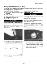
Engine Oil Level
Clean, Check
125
O
Engine Valve Lash(Diesel E/G Only)
Check, Adjust
118
O
Forks Inspect
162
O
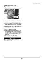
Fuel Filter
Change
150
O
Fuel Lines & Fittings
Check
152
O
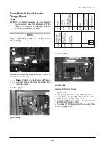
Fuses, Bulbs & Circuit Breaker
Change, Reset
121
O
Horn & Lights(If Equipped)
Check
148
O
Hydraulic Oil
Check, Clean, Change
164
Hydraulic Oil Level
Check
139
O O
Hydraulic Return Filter
Change
135, 152
O O
Inching & Brake Control Shaft
Lubricate
148
O
Lift Chains
Test, Check, Adjust
153
O
Mast Carriage, Lift Chains & Attachments
Check, Lubricate
140
O
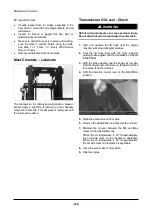
Mast Channels
Lubricate
128
O
Mast Hinge Pins
Lubricate
144
O
Overhead Guard
Inspect
149
O
Oxygen Sensor
Change
166
O
Parking Brake
Test, Adjust
133, 147
O O
Replace PCV Valve and breather element
(LP-Gas Engine Only)
Change 165
O
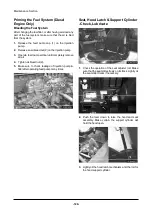
Seat, Hood Latch & Support Cylinder
Check, Lubricate
121
O
Steer Suspension
Inspect
149
O
Steer Wheel Bearings
Reassemble
159
O
Steering Mechanism
Check, Lubricate
141
O
Tilt Cylinders
Check, Adjust, Lubricate
145
O
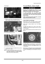
Tires & Wheels
Inspect, Check
123
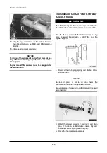
Transmission Oil, Oil Filter & Strainer
Clean, Change
130, 152
O O
Universal Joint(Diesel E/G Only)
Inspect
155
O
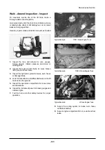
Walk-Around Inspection
Inspect
127
Water Separator(Diesel E/G Only)
Drain
118
O
Wheel Bolts & Nuts
Inspect
143
O
Содержание D35S-2
Страница 31: ...Safety Section 29 Lean away from the direction of fall Lean forward...
Страница 39: ...General Section 37 Capacity Chart...
Страница 40: ...General Section 38 Capacity Chart...
Страница 41: ...General Section 39 Capacity Chart with Side Shifter...
Страница 42: ...General Section 40 Capacity Chart with Side Shifter...
Страница 43: ...General Section 41 Capacity Chart...
Страница 44: ...General Section 42 Capacity Chart...
Страница 45: ...General Section 43 Capacity Chart with Side Shifter...
Страница 46: ...General Section 44 Capacity Chart with Side Shifter...
Страница 47: ...General Section 45 Capacity Chart D G 50C 2...
Страница 48: ...General Section 46 Capacity Chart with Side Shifter D G 50C 2...


