4
For SECAM L and L’ the TDA9361/TDA9381 is switched to positive modulation via I2C bus. SECAM L’ transmission only occur
in VHF band I and have their picture and sound carrier interchanged, compared to SECAM L and PAL B/G channels. For
SECAM L’ the picture carrier is situated at 33.9 MHz and the AM sound carrier at 40.40 MHz. The IF PLL reference is tuned
from 38.9 to 33.9 MHz, this is done via I2C Bus and the SIF filter is switched from channel 2 to channel 1; this is done by pin 4
of TDA 9361.
The tuner AGC time constant is slower for positive than for negative modulation, because the TDA9361 reduces its AGC cur-
rent. To make the AGC time constant even slower an extra series resistor R103 is added. To prevent IF overload when jumping
from a very strong transmitter to a weak transmitter a diode D101 has been added
************************************************************************************************************************************************
The SAW filter ( SF1 ) has a double Nyquist slope at 38.9 MHz and 33.9 MHz needed for this multistandard application.
The disadvantage of this choice is that a 5.5 MHz trap filter ( Z501 ) is needed to suppress the residual sound carrier in the
video for B/G signals.
************************************************************************************************************************************************
3. Source switching
Video :
The TDA9361/TDA9381 has only one external video input. The SCART video in pin (#20) is connected to the front RCA video
input.
The controlling software via I2C bus selects the signal source :
- Video signal from tuner ( Pin 40 ).
- External video.
- External SVHS from SCART.
The sound source switching is done in the video processor part and in the AM demodulator by the
µ
-Controller via I2C
bus.
The video processor pin 28 has multiple functions and provides in this application
- Deemphasis time constant
- Audio monitor output
- External AM input
- Deemphasis time constant : The time constant is given by the capacitor C504, needed to obtain the 54
µ
s time constant
for standard PAL signal.
- Audio monitor output : the nominal output signal is 500 mVrms, for all standards. The signal is also internally connected
through to the audio switch. This signal is not controlled by the volume setting and can be used for SCART audio output.
The signal is buffered to avoid influencing the deemphasis time constant and to adjust the output level.
- External AM input : By software the deemphasis pin can be converted into an input pin. External AM signal for SECAM
L/L’ is directly connected to this pin. In this configuration the FM sound is internally muted, DC level remains at 3Vdc.
An external sound signal of 500mVrms is applied to pin 35 via a coupling capacitor. The input impedance of this pin is
25K
Ω
typical. Switching between internal FM, external AM or external audio from SCART is controlled internally by soft-
ware.
FUNCTIONAL DESCRIPTION
APPENDIX
Содержание DTA-14V1
Страница 26: ...6 CIRCUIT BLOCK DIAGRAM...
Страница 29: ......
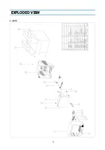
Страница 30: ...10 EXPLODED VIEW 1 14V3...
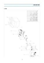
Страница 31: ...11 EXPLODED VIEW 2 20V3...
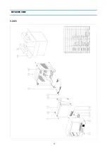
Страница 32: ...12 EXPLODED VIEW 3 21V3...
Страница 33: ...13 PRINTED CIRCUIT BOARD CIRCUIT DIAGRAM 6 SERVO SYSCON CEC CIRCUIT DIAGRAM T DECK...
Страница 59: ...19 IC DESCRIPTION APPENDIX...
Страница 62: ...22 APPENDIX IC DESCRIPTION...

