background image

15

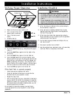
Verifying Proper Operation

Make sure the main power switch is off.

1. 

Turn on power at the circuit 

2. 

breaker panel or fuse box.
Turn on the main power 

3. 

switch.
Install the filter(s).

4. 

Touch the 

5. 

lights

 feature key. Verify that all the lights 

come on.
Touch the 

6. 

lights

 key again to turn the lights to the 

low setting.
Touch the 

7. 

light

S key again to turn the lights off.

Touch the 

8. 

fAn

 feature key once and release. Verify 

that one light is showing on the fan speed indicator and 

that the fan is on at low speed. Touch and release the 

fAn

 key repeatedly, three times. Verify that with each 

touch of the key, the number of lights on the fan speed 

indicator increases and that the fan speed increases.
Touch the 

9. 

fAn

 key again to turn the fan off.

If the hood fails to operate properly:

Verify that power is supplied to the hood.

• 

Check the electrical connections to ensure that the 

• 

installation has been completed correctly.
Repeat the above test.

• 

If the hood still does not work, contact Dacor Distinctive 

• 

Service at (877) 337-3226. Do not attempt to repair the 

appliance yourself. If you need service, be sure to have 

the model and serial numbers available when you call. 

See the inside cover for location.

Do not attempt to repair the appliance yourself. Dacor 

is not responsible for service required to correct a faulty 

installation.

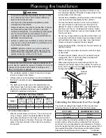
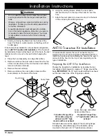
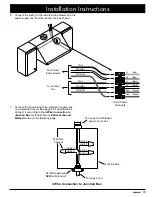
Installation Instructions

Installation Checklist

 wArning

To ensure a safe and proper installation, the follow-

• 

ing checklist should be completed by the installer to 

ensure that no part of the installation has been over-

looked.
Proper installation is the responsibility of the hom-

• 

eowner. The importance of proper installation of your 

Dacor range hood cannot be overemphasized.

Is the hood properly attached to the wall according to 


the instructions on page 12?

Is the duct work completely installed? Are all joints 


attached with sheet metal screws and wrapped with 

duct tape? See page 12.

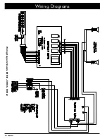
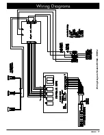
Is the range hood wired and grounded according to 


these instructions and in accordance with all applicable 

electrical codes? See Page 12.

Are the filters properly installed according to the use 


and care manual?

Has proper operation been verified?


Has the warranty been activated on-line or the warranty 


card been filled out completely and mailed?
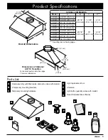
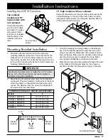
Feature Keys

Main Power 

Switch

Filters

ON

OFF

Содержание EHR3012

Страница 1: ...er For use with models EHR30 EHR36 EHR42 EHR48 EHR54 Part No 103781 Rev D Approved for use with all dacor ranges and cooktops Tested in accordance with the latest edition of ANSI UL 507 standard for e...

Страница 2: ...completely and care fully before you begin the installation process Leave these installation instructions with the customer Customer Keep these installation instructions for future reference and the l...

Страница 3: ...amage personal injury or death warning WARNING TO REDUCE THE RISK OF FIRE ELECTRIC SHOCK OR INJURY TO PERSONS OBSERVE THE FOLLOWING Use this unit only in the manner intended by the manufacturer If you...

Страница 4: ...ning device such as a tag to the electrical panel Read the use and care manual completely before using the appliance Clean the appliance only as instructed in the use and care manual Use only the clea...

Страница 5: ...ac 75 W halogen Model Specific Model Number EHR48 EHR54 EHR42 EHR30 EHR36 Lights 3 2 2 Filters 4 3 2 Exhaust Outputs 2 1 1 Product Specifications Weight Specifications Model Weight EHR3012 39 lbs 18 k...

Страница 6: ...mensions Dual exhaust models Standard 8 duct connection Single exhaust models Standard 8 duct connection Front of hood 1 3 8 cm 3 7 6 cm 4 10 2 cm 9 7 8 25 1 cm 6 1 8 15 6 cm 19 50 2 cm Electrical acc...

Страница 7: ...6 cm EHR5418 53 7 8 136 8 cm See diagram on facing page A Parts List Hood assembly with filters size and style varies with model 2 temporary mounting brackets Temporary mounting hardware A B C D Ligh...

Страница 8: ...ceeded Dimensions shown provide minimum clearances unless otherwise noted All contact surfaces between the hood and any cabi nets or walls must be solid and at right angles Install the range hood and...

Страница 9: ...e duct work and connecting it to the hood on one end and the remote blower on the other There are 7 8 access holes in the top and back of the hood for connecting the conduit The customer must supply c...

Страница 10: ...missing or damaged please contact the dealer immedi ately Do not install a damaged or incomplete appliance Make sure you have everything necessary for proper instal lation before proceeding Mounting L...

Страница 11: ...alfway between the cabinets at the installation location or the same as the center line of the cooktop or range The line will be used to line up the mounting brackets during installa tion Locate the c...

Страница 12: ...Remove the duct collar s 4 Remove and save the cover plate screws and the 5 cover plate s on the back of the hood Using the existing screws attach the cover plate 6 removed in step 5 to the top of the...

Страница 13: ...g sheet metal screws not included Seal the base of of the transition with duct tape 2 1 8 Bracket location Bracket location Hood location F F Reinforced Drywall Top mounting shown Mounting Bracket Ins...

Страница 14: ...om the hood and working 2 toward the remote blower Observe the specifications on page 7 and 8 Fasten all joints with sheet metal screws and seal with 3 duct tape or certified silver tape Final Electri...

Страница 15: ...om the junction box as shown GREEN GREEN WHITE WHITE BLACK BLACK 3 Wire Connection to Junction Box UL CSA approved NEMA strain relief To house circuit breaker panel or fuse box To range hood Junction...

Страница 16: ...ssure continuity to ground See above UL CSA approved NEMA strain relief Fasten clamp tightly on pipe Separate No 10 minimum copper ground wire To house circuit breaker panel or fuse box To range hood...

Страница 17: ...the appliance yourself If you need service be sure to have the model and serial numbers available when you call See the inside cover for location Do not attempt to repair the appliance yourself Dacor...

Страница 18: ...N G GREEN V VIOLET W Y W Y B B B B W W R R R BL BL G G G G R W W W W W W W W W W R Y B W W 10 9 8 7 6 5 4 3 2 1 10 9 8 7 6 5 4 3 2 1 REMOTE FAN BOARD P1 P2 P3 P4 MICROPROCESSOR PROGRAMMING HEADER P3 2...

Страница 19: ...WN G GREEN V VIOLET W Y W Y R W Y R W W W W W W W W W W R Y B W W 10 9 8 7 6 5 4 3 2 1 10 9 8 7 6 5 4 3 2 1 REMOTE FAN BOARD P1 P2 P3 P4 MICROPROCESSOR PROGRAMMING HEADER P3 2 4 6 8 10 1 3 5 7 9 CONTR...

Страница 20: ...Dacor 1440 Bridge Gate Drive Diamond Bar CA 91765 Tel 800 793 0093 FAX 626 403 3130 www Dacor com...

Отзывы: