Dacor EHR3012 Скачать руководство пользователя страница 9

7

Planning the Installation

 wArning

To prevent combustion by-products, smoke or odors 

• 

from entering the home and to improve efficiency, 

tape all duct joints securely.
Use only duct work deemed acceptable by state, 

• 

municipal and local codes.
Range hoods may interrupt the proper flow of smoke 

• 

and combustion gases from furnaces, gas water 

heaters and fireplaces. To avoid drawing lethal gases 

into the home, follow the manufacturer’s recom-

mendation for these devices and consult NFPA and 

ASHRAE recommendations.
Failure to install a remote blower or proper duct work 

• 

may result in a back draft and/or the insufficient vent-

ing of smoke and fumes.

do not

• 

 install more than one in-line or external 

blower to increase the length of the duct run. Even 

small differences between blower air flow rates can 

greatly reduce the air draw by the hood.

 cAution

To reduce the risk of fire and to properly exhaust air, be 

sure to duct air outside the house or building. Do not vent 

exhaust air into spaces within walls or ceilings or into 

attics, crawl spaces or garages.

The ventilation system consists of hood and a single 

• 

remote or single in-line blower. 
A Dacor remote or in-line blower must be installed for 

• 

the hood to operate properly. Only one blower shall be 

installed. 
The EHR series hoods cannot be installed with any 

• 

other blower type than the models indicated below. For 

directions on installing the blower, see the REMP3/16, 

ILHSF8/10 installation instructions.

Approved dAcor Blowers  

for use with ehr series hoods

Model

reMp3* 

(remote)


600 CFM

ilhsf8* 

(in-line)


600 CFM

reMp16* 

(remote)


1000 CFM

ilhsf10* 

(in-line)


1200 CFM

EHR30/36/42

X

X

X

X

EHR48/54

X

X

* At 0 inches static pressure

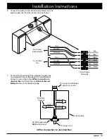
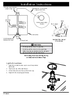
Wire the remote blower to turn on. The vent is turned 

• 

on by running a piece of conduit parallel to the duct 

work and connecting it to the hood on one end and 

the remote blower on the other. There are 7/8” access 

holes in the top and back of the hood for connecting 

the conduit.

The customer must supply conduit with minimum cur-

• 

rent carrying capacity of 8 Amps to supply power to the 

remote blower from the hood.
All duct work materials (including screws and duct tape) 

• 

must be purchased separately by the customer.
The hood exhaust connects to an 8-inch round duct. 

• 

You can increase the duct size over the duct run if 

desired. To prevent a back draft, never decrease the 

duct size over the run. If existing duct work is smaller 

than 8 inches in diameter, remove it and replace it with 

8-inch duct work.
Do not rely on tape alone to seal duct joints. Fasten all 

• 

connections with sheet metal screws and tape all joints 

with certified silver tape or duct tape. Use sheet metal 

screws as require to support the duct weight.
To prevent back-drafts, a damper at the duct outlet may 

• 

also be required.
Make sure duct work does not interfere with floor joists 

• 

or wall studs.
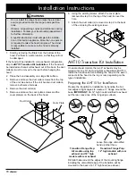
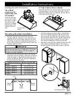
On dual exhaust models, the two 8” exhausts may be 

• 

merged into one 10” duct using Dacor transition kit 

AHT10. See page 10 for details.
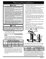
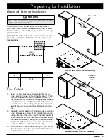
When planning new duct work, always look for the 

• 

shortest, most direct route to the outside. The duct col-

lar can be moved to accommodate venting (and wiring) 

through the top 

 A 

 or the back 

 B 

.

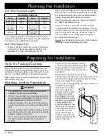
Calculating the Maximum Duct Run Length

The maximum straight duct length for the hood is deter-

mined by the type of duct used. See the chart below.

duct siZe

MAXiMuM duct run

8” round

60 feet

10” round

50 feet

For each elbow and transition added to the duct work, a 

certain number of feet must be subtracted from the maxi-

mum duct run to compensate for wind resistance. To deter-

mine the length the duct work cannot exceed, subtract all of 

the equivalent lengths of the elbows and transitions listed 

below from the maximum duct run above.       Continued...

Conduit

Conduit

Remote 

Blower

Remote 

Blower

A

B

Содержание EHR3012

Страница 1: ...er For use with models EHR30 EHR36 EHR42 EHR48 EHR54 Part No 103781 Rev D Approved for use with all dacor ranges and cooktops Tested in accordance with the latest edition of ANSI UL 507 standard for e...

Страница 2: ...completely and care fully before you begin the installation process Leave these installation instructions with the customer Customer Keep these installation instructions for future reference and the l...

Страница 3: ...amage personal injury or death warning WARNING TO REDUCE THE RISK OF FIRE ELECTRIC SHOCK OR INJURY TO PERSONS OBSERVE THE FOLLOWING Use this unit only in the manner intended by the manufacturer If you...

Страница 4: ...ning device such as a tag to the electrical panel Read the use and care manual completely before using the appliance Clean the appliance only as instructed in the use and care manual Use only the clea...

Страница 5: ...ac 75 W halogen Model Specific Model Number EHR48 EHR54 EHR42 EHR30 EHR36 Lights 3 2 2 Filters 4 3 2 Exhaust Outputs 2 1 1 Product Specifications Weight Specifications Model Weight EHR3012 39 lbs 18 k...

Страница 6: ...mensions Dual exhaust models Standard 8 duct connection Single exhaust models Standard 8 duct connection Front of hood 1 3 8 cm 3 7 6 cm 4 10 2 cm 9 7 8 25 1 cm 6 1 8 15 6 cm 19 50 2 cm Electrical acc...

Страница 7: ...6 cm EHR5418 53 7 8 136 8 cm See diagram on facing page A Parts List Hood assembly with filters size and style varies with model 2 temporary mounting brackets Temporary mounting hardware A B C D Ligh...

Страница 8: ...ceeded Dimensions shown provide minimum clearances unless otherwise noted All contact surfaces between the hood and any cabi nets or walls must be solid and at right angles Install the range hood and...

Страница 9: ...e duct work and connecting it to the hood on one end and the remote blower on the other There are 7 8 access holes in the top and back of the hood for connecting the conduit The customer must supply c...

Страница 10: ...missing or damaged please contact the dealer immedi ately Do not install a damaged or incomplete appliance Make sure you have everything necessary for proper instal lation before proceeding Mounting L...

Страница 11: ...alfway between the cabinets at the installation location or the same as the center line of the cooktop or range The line will be used to line up the mounting brackets during installa tion Locate the c...

Страница 12: ...Remove the duct collar s 4 Remove and save the cover plate screws and the 5 cover plate s on the back of the hood Using the existing screws attach the cover plate 6 removed in step 5 to the top of the...

Страница 13: ...g sheet metal screws not included Seal the base of of the transition with duct tape 2 1 8 Bracket location Bracket location Hood location F F Reinforced Drywall Top mounting shown Mounting Bracket Ins...

Страница 14: ...om the hood and working 2 toward the remote blower Observe the specifications on page 7 and 8 Fasten all joints with sheet metal screws and seal with 3 duct tape or certified silver tape Final Electri...

Страница 15: ...om the junction box as shown GREEN GREEN WHITE WHITE BLACK BLACK 3 Wire Connection to Junction Box UL CSA approved NEMA strain relief To house circuit breaker panel or fuse box To range hood Junction...

Страница 16: ...ssure continuity to ground See above UL CSA approved NEMA strain relief Fasten clamp tightly on pipe Separate No 10 minimum copper ground wire To house circuit breaker panel or fuse box To range hood...

Страница 17: ...the appliance yourself If you need service be sure to have the model and serial numbers available when you call See the inside cover for location Do not attempt to repair the appliance yourself Dacor...

Страница 18: ...N G GREEN V VIOLET W Y W Y B B B B W W R R R BL BL G G G G R W W W W W W W W W W R Y B W W 10 9 8 7 6 5 4 3 2 1 10 9 8 7 6 5 4 3 2 1 REMOTE FAN BOARD P1 P2 P3 P4 MICROPROCESSOR PROGRAMMING HEADER P3 2...

Страница 19: ...WN G GREEN V VIOLET W Y W Y R W Y R W W W W W W W W W W R Y B W W 10 9 8 7 6 5 4 3 2 1 10 9 8 7 6 5 4 3 2 1 REMOTE FAN BOARD P1 P2 P3 P4 MICROPROCESSOR PROGRAMMING HEADER P3 2 4 6 8 10 1 3 5 7 9 CONTR...

Страница 20: ...Dacor 1440 Bridge Gate Drive Diamond Bar CA 91765 Tel 800 793 0093 FAX 626 403 3130 www Dacor com...

Отзывы: