DXS-3350SR Gigabit Layer 3 Switch
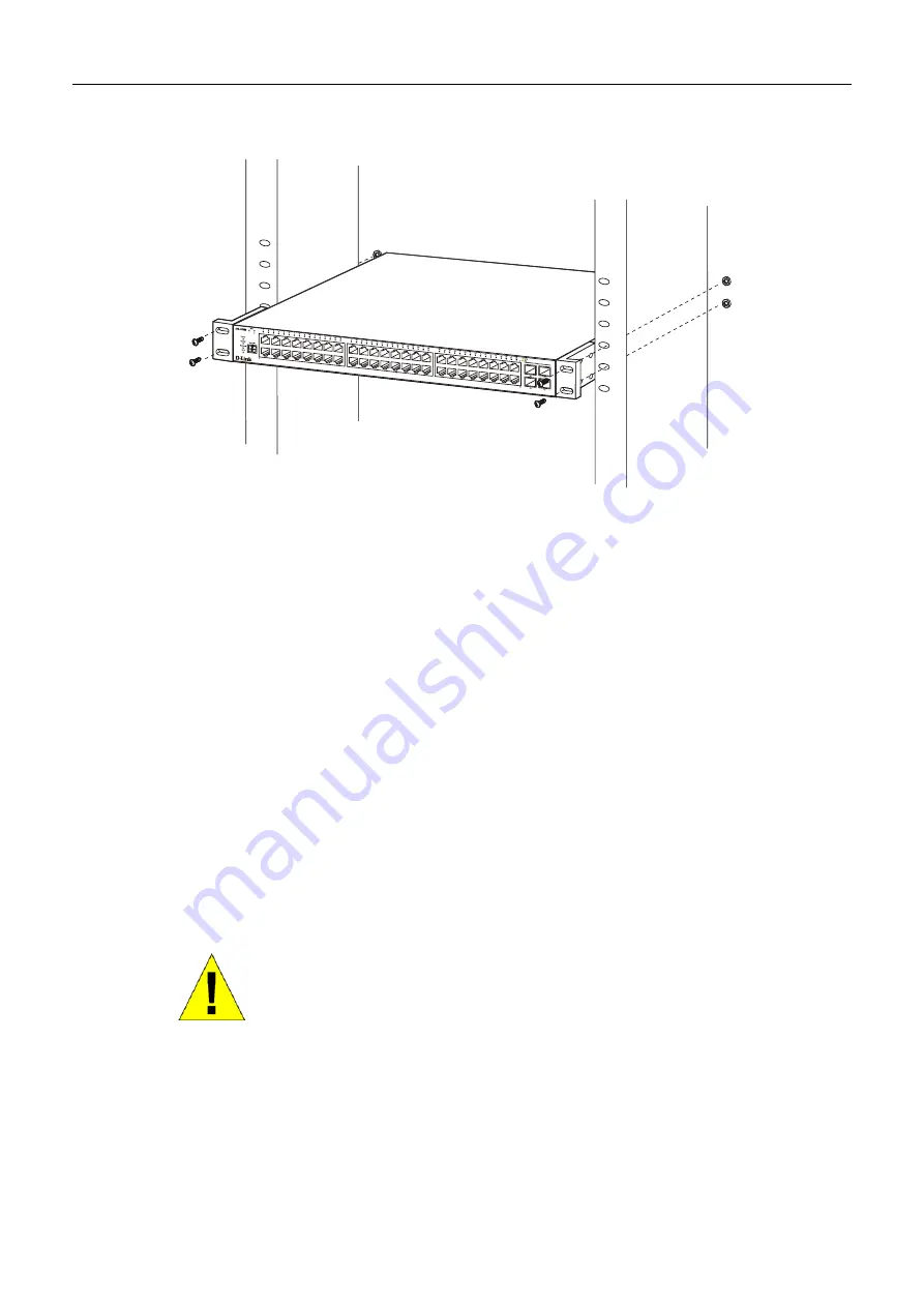
Mounting the Switch in a Standard 19" Rack
Figure 2- 3. Installing Switch in a rack
Power On
Plug one end of the AC power cord into the power connector of the Switch and the other end into the local power source
outlet.
After the Switch is powered on, the LED indicators will momentarily blink. This blinking of the LED indicators represents a
reset of the system.
Power Failure
As a precaution, in the event of a power failure, unplug the Switch. When power is resumed, plug the Switch back in.
The Optional Module
At the rear of the DXS-3350SR resides an optional module slot. This slot may be equipped with a 2-port 10GE XFP Uplink
Module, sold separately. Adding the DEM-420X optional module will allow the administrator to add 2 fibre-optic ports
which will transmit information at a rate of 10 gigabits a second. These two ports are compliant with standard IEEE
802.3ae, support full-duplex transmissions only and can be used with XFP MSA compliant transceivers. To install the
module in the DXS-3350SR, follow the simple steps listed below.
CAUTION
: Before adding the optional module, make sure to disconnect all power
sources connected to the Switch. Failure to do so may result in an electrical shock
which may cause damage, not only to the individual but to the Switch as well.
15
Содержание xStack DXS-3350SR
Страница 114: ...DXS 3350SR Gigabit Layer 3 Switch Figure 6 56 Access Profile Configuration IP 105 ...
Страница 118: ...DXS 3350SR Gigabit Layer 3 Switch Figure 6 59 Access Rule Configuration window IP window 109 ...
Страница 123: ...DXS 3350SR Gigabit Layer 3 Switch Figure 6 65 Access Rule Configuration Packet Content Mask 114 ...
Страница 125: ...DXS 3350SR Gigabit Layer 3 Switch Figure 6 66 Access Rule Display Packet Content 116 ...
Страница 129: ...DXS 3350SR Gigabit Layer 3 Switch Figure 6 70 Second 802 1X Authenticator Settings menu 120 ...
Страница 284: ......