DXS-3410 Series
Layer 3 Stackable Managed Switch
Hardware Installation Guide
17
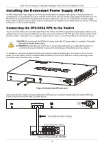
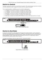
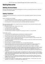
Switch to Switch
The Switch can be used to connect to any other Switch in the network. This network topology is used when this Switch
or the other switch does not have enough ports to cater for all the end nodes in the network.
There is significant flexibility in establishing connections using the suitable cabling:
For 100BASE-TX connections to the Switch, use Category 5e UTP/STP cables.
For 1000BASE-T connections to the Switch, use Category 5e/6 UTP/STP cables.
For 2.5GBASE-T connections to the Switch, use Category 5e/6 UTP/STP cables.
For 5GBASE-T connections to the Switch, use Category 5e/6 UTP/STP cables.
For 10GBASE-T connections to the Switch, use Category 6a/7 UTP/STP cables.
For fiber optic connections to the Switch's SFP+/SFP28 ports, make use of the appropriate fiber optic cables.
Figure 4-3 Switch to another Switch/Hub
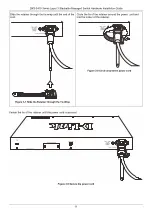
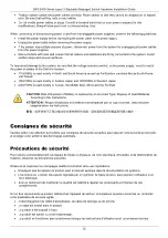
Switch to End Node
An end node is a general term for edge networking devices that will be linked to this Switch. Common examples of
end nodes include Servers, Personal Computers (PCs), Notebooks, Access Points, Print Servers, VoIP Phones, and
more. Each end node should have an RJ45 networking port. Typically, end nodes will connect to this Switch using a
standard twisted-pair UTP/STP network cable. Upon a successful connection, the corresponding port light will
illuminate and blink, signifying network activity on that port.
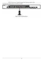
The diagram below displays a typical end node (normal PC) connected to the Switch.
Figure 4-4 Switch to End Node (Client)
Содержание DXS-3410 Series
Страница 1: ...Version 1 00 2023 12 18...
Страница 54: ......


