DWR-500 Quick Installation Guide
4
Cable Color
Pin Mapping
White/green
Pin 1
Green
Pin 7
White/orange Pin 5
Orange
Pin 4
White/blue
Pin 2
Blue
Pin 3
White/brown
Pin 6
Brown
Pin 8
Ground
Pin 9
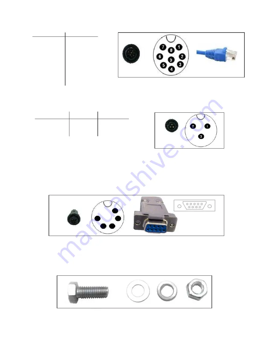
Figure 3. Ethernet cable connector and RJ45 for DWR-500
Power Cable
The weather insulated power cable connector is seen in the Figure 4.
Color Code
Function
Pin Mapping
White (Yellow) Ground
Pin 1
Red
Live
Pin 2
Black (Green)
Neutral
Pin 3
Figure 4. Power cable connector for DWR-500
Console Cable
The weather insulated end of the console cable is shown on the left in the Figure 5. The right shows the pin
mapping. The other end of the console cable to connect to the laptop has a normal DB9 connector.
Figure 5. Console Cable Connector and DB9 connector for DWR-500
Screws
10 screws and nuts are provided. These are standard M6 X 16.
Figure 6. Standard Screws used for installation of DWR-500


