background image

foregoing limitations and exclusions may not apply. This limited warranty provides 
specific legal rights and the product owner may also have other rights which vary 
from state to state. 

Trademarks:  

D-Link is a registered trademark of D-Link Systems, Inc. Other 

trademarks or registered trademarks are the property of their respective 
manufacturers or owners.

Copyright Statement:  

No part of this publication or 

documentation accompanying this Product may be 
reproduced in any form or by any means or used to 
make any derivative such as translation, transformation, 
or adaptation without permission from D-Link 
Corporation/D-Link Systems, Inc., as stipulated by the 
United States Copyright Act of 1976.  Contents are 
subject to change without prior notice.  Copyright

©

 2005 

by D-Link Corporation/D-Link Systems, Inc. All rights 
reserved.

CE Mark Warning:  

This is a Class A product. In a domestic environment, this 

product may cause radio interference, in which case the user may be required to 
take adequate measures. 

FCC Statement:  

This equipment has been tested and found to comply with the 

limits for a Class A digital device, pursuant to part 15 of the FCC Rules. These limits 
are designed to provide reasonable protection against harmful interference in a 
residential installation. This equipment generates, uses, and can radiate radio 
frequency energy and, if not installed and used in accordance with the instructions, 
may cause harmful interference to radio communication. However, there is no 
guarantee that interference will not occur in a particular installation. If this equipment 
does cause harmful interference to radio or television reception, which can be 
determined by turning the equipment off and on, the user is encouraged to try to 
correct the interference by one or more of the following measures

:

x

Reorient or relocate the receiving antenna. 

x

Increase the separation between the equipment and receiver. 

x

Connect the equipment into an outlet on a circuit different from that to which the 
receiver is connected. 

x

Consult the dealer or an experienced radio/TV technician for help. 

For detailed warranty outside the United States, please contact 
corresponding local D-Link office.  

Содержание DI-713

Страница 1: ...D Link DI 713 User s Manual ...

Страница 2: ...ork Settings to the Computer 8 Chapter 4 Configuring the DI 713 9 4 1 Start up and Log in 9 4 2 Status 10 4 4 Primary Setup 12 4 5 DHCP Server 14 4 6 Virtual Server 15 4 7 Special AP 16 4 8 Access Control 17 4 9 Misc Items 18 4 10 Wireless Setting 19 Appendix A TCP IP Configuration for Windows 95 98 20 A 1 Install TCP IP Protocol into Your PC 20 A 2 Set TCP IP Protocol for Working with the DI 713 ...

Страница 3: ...rate with auto fallback Broadband modem and IP sharing Connects multiple computers to a broadband Cable or DSL modem or an Ethernet router to share the Internet connection Auto sensing Ethernet Switch Equipped with a 3 port 10 100 auto sensing Ethernet switch VPN supported Supports multiple PPTP sessions and allows setup of a VPN server and VPN clients Firewall All unwanted packets from outside in...

Страница 4: ... networked computer to be fully exposed to the Internet this function is used when the special application sensing tunnel feature is insufficient to allow an application to function correctly 1 2 Packing List One DI 713 wireless broadband router unit One power adapter Two CAT 5 UTP Straight through Fast Ethernet cable One CD with HTML Quick Installation Guide and PDF User s Manual One Quick Instal...

Страница 5: ...stic LED indicators The WAN port connects your DSL or cable modem to the router The LAN ports are used to connect to your computers or other network devices LEDs monitor the status of each port Figure 2 1 Front Panel Port WAN the port where you will connect your Cable or DSL modem or Ethernet router Port 1 3 the ports where you will connect networked computers and other devices ...

Страница 6: ... or receiving data On The LAN port is linked LAN LAN port activity Green Blinking The LAN port is sending or receiving data W Link Backbone activity Green Blinking Sending or receiving data from wireless to wired backbone W Act Wireless activity Green Blinking Sending or receiving data via wireless On An active station is connected to the corresponding LAN port Link Act 1 3 Link status Green Blink...

Страница 7: ...ere to place your Wireless Broadband Router You can place your Wireless Broadband Router on a desk or other secure surface or you can mount it on a wall For optimal performance place your Wireless Broadband Router in the center of your office or your home in a location that is away from any potential source of interference such as a metal wall or microwave oven This location must be close to power...

Страница 8: ...s of the DI 713 b Wireless LAN connection make sure the antennas are in a vertical position if not rotate over 90 degrees 3 Setup WAN connection prepare an Ethernet cable for connecting the DI 713 to your cable xDSL modem or Ethernet backbone Figure 2 3 illustrates the WAN connection Figure 2 3 Setup of LAN and WAN connections for the DI 713 ...

Страница 9: ...utomatically enter the self test phase When it is in the self test phase the indicators M1 and M2 will be lit for about 10 seconds and then M1 and M2 will flash 3 times to indicate that the self test operation has finished Finally the M1 will continuously flash once per second to indicate that the DI 713 is in normal operation ...

Страница 10: ...nnected to the DI 713 The following example shows the ping procedure for Windows 95 platforms First execute the ping command from a DOS window ping 192 168 0 1 If the following messages appear Pinging 192 168 0 1 with 32 bytes of data Reply from 192 168 0 1 bytes 32 time 2ms TTL 64 a communication link between your computer and the DI 713 has been successfully established Otherwise if you get the ...

Страница 11: ...scape or Address for IE field and press ENTER For example http 192 168 0 1 After the connection is established you will see the web user interface of the DI 713 There are two appearances of web user interface for general users and for system administrator To log in as an administrator enter the system password the factory setting is admin in the System Password field and click on the Log in button...

Страница 12: ...port is assigned a dynamic IP address a Renew or Release button may appear You can click this button to manually renew or release the IP This screen also provides the Firmware Version and MAC Address information Pressing the Refresh button will update the Device Information screen to show the current status ...

Страница 13: ...word view log information reboot the DI 713 clone the MAC Address reset to default settings and perform a firmware upgrade Note we strongly recommend you to change the system password for security reasons If you forgot the system password please refer to Appendix A to reset a new one ...

Страница 14: ... You can change it to meet your need 2 WAN Type WAN connection type of your ISP You can click the Change button to choose the correct setting from the following four options A Static IP Address your ISP assigns you an IP address B Dynamic IP Address Obtain an IP address from your ISP automatically C PPP over Ethernet Some ISPs require the use of PPPoE to connect to their services This requires a U...

Страница 15: ...on t want to change the password keep it empty 2 PPPoE Service Name optional Input the service name if your ISP requires it 3 Maximum Idle Time the maximum time the connection is idle before you are disconnected from your ISP and your PPPOE session is terminated 4 4 4 Dial up Network 1 Dial up Telephone Account and Password assigned by your ISP If you don t want to change the password keep it empt...

Страница 16: ... to configure of your computers to automatic receive IP settings mode then when your computer is powered on it will automatically load the proper TCP IP settings from the DI 713 The settings of DHCP server options include the following items 1 DHCP Server Choose Disable or Enable 2 Range of IP Address Pool Whenever there is a request the DHCP server will automatically allocate an unused IP address...

Страница 17: ...he Virtual Server Mapping A virtual server is defined as a Service Port and all requests to this port will be redirected to the computer specified by the Server IP For example if you have an FTP server port 21 at 192 168 0 5 a Web server port 80 at 192 168 0 7 and a VPN server at 192 168 123 10 then you need to specify the following virtual server mapping table Service Port Server IP Enable 21 192...

Страница 18: ... is still insufficient to allow an application to function correctly try DMZ host in the Misc Items options 1 Trigger the outbound port number the application issued first 2 Incoming Ports when the trigger packet is detected the inbound packets to the specified port numbers are allowed to pass the firewall The DI 713 provides some predefined settings in the gray pad on the bottom of the web page C...

Страница 19: ...ights can allow or block users to access specified TCP and UDP ports For example If you want IP addresses 50 99 to block access to port 21 and 119 you would insert 50 99 into the Group 1 members box Change the Ports drop down box to Block and type 21 119 into the box to the right of the Block box Group Members Access Right Comments Default Allow No access rights allow nothing Group 1 50 99 Allow 2...

Страница 20: ...Remote Administrator Host In general only Intranet user can browse the built in web pages to perform administration tasks This feature enables you to perform administration tasks from a remote host If this feature is enabled only the specified IP address can perform remote administration If the specified IP address is 0 0 0 0 any host can connect to the DI 713 to perform administration task When t...

Страница 21: ... The factory setting is default 2 Channel The radio channel number The permissible channels depend on the Regulatory Domain The factory setting is channel 6 3 Security Select the data privacy algorithm you want Enabling the security can protect your data while it is transferred from one station to another The standardized IEEE 802 11 WEP based on a 40 bit shared key is used here When you enable th...

Страница 22: ...you have successfully installed one network card or wireless adapter on your personal computer If not please refer to your network card manual Moreover the Section A 2 tells you how to set TCP IP values for working with the DI 713 correctly A 1 Install TCP IP Protocol into Your PC 1 Click the Start button and choose Settings then click Control Panel 2 Double click the Network icon and select the C...

Страница 23: ...he OK button to return to the Network window 6 The TCP IP protocol will be listed in the Network window Click OK to complete the install procedure and restart your PC to enable the TCP IP protocol A 2 Set TCP IP Protocol for Working with the DI 713 1 Click the Start button and choose Settings then click Control Panel ...

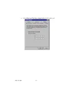
Страница 24: ...the TCP IP line that has been associated to your network card in the Configuration tab of the Network window 3 Click the Properties button to set the TCP IP protocol for the DI 713 4 You have two setting methods to choose from A Get IP via DHCP server or ...

Страница 25: ...REV 101404 23 a Select Obtain an IP address automatically in the IP Address tab ...

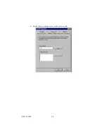
Страница 26: ...REV 101404 24 b Make sure no settings are set in the Gateway tab ...

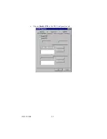
Страница 27: ...REV 101404 25 c Choose Disable DNS in the DNS Configuration tab ...

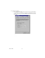
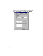
Страница 28: ...P manually a Select Specify an IP address in the IP Address tab The default IP address of the DI 713 is 192 168 0 1 So please use 192 168 0 xxx xxx is between 2 and 254 for IP Address field and 255 255 255 0 for Subnet Mask field ...

Страница 29: ...REV 101404 27 b In the Gateway tab add the IP address of the DI 713 default IP is 192 168 0 1 in the New gateway field and click Add button ...

Страница 30: ...REV 101404 28 c In the DNS Configuration tab add the DNS values which are provided by the ISP into DNS Server Search Order field and click Add button ...

Страница 31: ...nk Technical Support over the Telephone 877 453 5465 24 hours a day seven days a week D Link Technical Support over the Internet http support dlink com email support dlink com Tech Support for customers within Canada D Link Technical Support over the Telephone 800 361 5265 Monday to Friday 7 30am to 12 00am EST D Link Technical Support over the Internet http support dlink ca email support dlink ca...

Страница 32: ...ten Sie beim Anschluß an das Stromnetz die Anschlußwerte 9 Die Netzanschlußsteckdose muß aus Gründen der elektrischen Sicherheit einen Schutzleiterkontakt haben 10 Verlegen Sie die Netzanschlußleitung so daß niemand darüber fallen kann Es sollete auch nichts auf der Leitung abgestellt werden 11 Alle Hinweise und Warnungen die sich am Geräten befinden sind zu beachten 12 Wird das Gerät über einen l...

Страница 33: ... BY OPERATION OF LAW STATUTORY OR OTHERWISE INCLUDING WARRANTIES OF MERCHANTABILITY AND FITNESS FOR A PARTICULAR PURPOSE D LINK NEITHER ASSUMES NOR AUTHORIZES ANY OTHER PERSON TO ASSUME FOR IT ANY OTHER LIABILITY IN CONNECTION WITH THE SALE INSTALLATION MAINTENANCE OR USE OF D LINK S PRODUCTS D LINK SHALL NOT BE LIABLE UNDER THIS WARRANTY IF ITS TESTING AND EXAMINATION DISCLOSE THAT THE ALLEGED DE...

Страница 34: ... When D Link provides replacement then the defective product becomes the property of D Link Warranty service may be obtained by contacting a D Link office within the applicable warranty period and requesting a Return Material Authorization RMA number If a Registration Card for the product in question has not been returned to D Link then a proof of purchase such as a copy of the dated purchase invo...

Страница 35: ...arranty but shall not apply to any update or replacement which may be provided for download via the Internet or to any update which may otherwise be provided free of charge D Link s sole obligation under this software warranty shall be to replace any defective software product with product which substantially conforms to D Link s applicable product documentation Purchaser assumes responsibility fo...

Страница 36: ...rvice Office The replacement Hardware need not be new or have an identical make model or part D Link may in its sole discretion replace the defective Hardware or any part thereof with any reconditioned product that D Link reasonably determines is substantially equivalent or superior in all material respects to the defective Hardware Repaired or replacement Hardware will be warranted for the remain...

Страница 37: ...The customer shall return the product to the original purchase point based on its return policy In case the return policy period has expired and the product is within warranty the customer shall submit a claim to D Link as outlined below x The customer must submit with the product as part of the claim a written description of the Hardware defect or Software nonconformance in sufficient detail to a...

Страница 38: ...G WITHOUT LIMITATION ANY WARRANTY OF MERCHANTABILITY FITNESS FOR A PARTICULAR PURPOSE AND NON INFRINGEMENT IF ANY IMPLIED WARRANTY CANNOT BE DISCLAIMED IN ANY TERRITORY WHERE A PRODUCT IS SOLD THE DURATION OF SUCH IMPLIED WARRANTY SHALL BE LIMITED TO NINETY 90 DAYS EXCEPT AS EXPRESSLY COVERED UNDER THE LIMITED WARRANTY PROVIDED HEREIN THE ENTIRE RISK AS TO THE QUALITY SELECTION AND PERFORMANCE OF ...

Страница 39: ...uate measures FCC Statement This equipment has been tested and found to comply with the limits for a Class A digital device pursuant to part 15 of the FCC Rules These limits are designed to provide reasonable protection against harmful interference in a residential installation This equipment generates uses and can radiate radio frequency energy and if not installed and used in accordance with the...

Страница 40: ...EPAIR LINE 00800 7250 8000 INDIA D LINKINDIA Plot No 5 Kurla Bandra Complex Road Off Cst Road Santacruz E Bombay 400 098 India TEL 91 22 652 6696 FAX 91 22 652 8914 URL www dlink india com E MAIL service dlink india com ITALY D LINKITALIA Via Nino Bonnet No 6 b 20154 Milano Italy TEL 39 02 2900 0676 FAX 39 02 2900 1723 URL www dlink it E MAIL info dlink it JAPAN D LINKJAPAN 10F 8 8 15 Nishi Gotand...

Страница 41: ...Product registration is entirely voluntary and failure to complete or return this form will not diminish your warranty rights ...

Отзывы: