7
Controls and Features
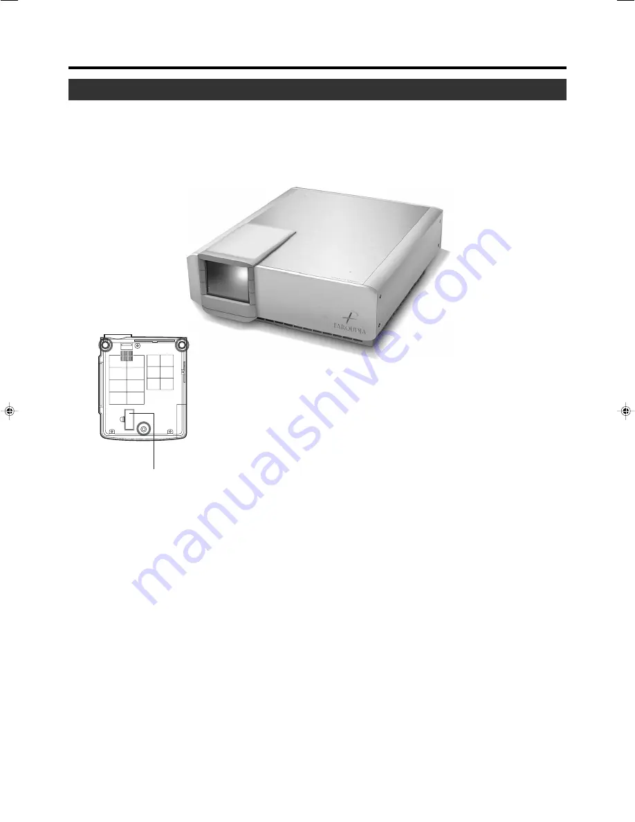
Front Side/Top Surface/Left Side
6.
Air inlets (on the front, right, and bottom side of
projector)
The air inlets absorb air to cool the internal components of
the projector. Do not block or allow warm air to blow into
them as it may cause damage.
* The air inlet filter on the right side cannot be removed.
Please clean the filter regularly with eg, a vacuum cleaner.
7.
Remote Sensor (Front)
When operating with the remote control, aim it towards this
sensor. (
☞
page 18)
* A remote sensor is also provided at the rear of the projec-
tor.
8. Zoom and
Focus Ring
Used to manually focus
and zoom
the image on the screen.
1.
Control Panel
For details, See ‘Control Panel on the Projector’.
2.
AC Power Input Terminal
This is where the supplied power cord is connected to.
3. Top and side covers
Remove to access lens and inputs
4.
Foot Lever (for front adjustable foot)
Use when extending and retracting the front foot.
5.
Lens
The lens is a 1.3 x manual zoom lens.
FDP-DILA3
uses 1:1 fixed lens
with an anamorphic
lens attachment.
3.
Remove four
end
screws
to access input board
3. Pull off
top
lens cover
to
access focus and zoom
1. Remove side cover to
access control panel
7. Remote sensor
4. Foot Lever
2. AC power terminal
5. Anamorphic Lens
8. Zoom and Focus ring
6. Air vents
Do not open
Filter
Adjustable foot


