CY8CKIT-031 PSoC® CapSense® Expansion Board Kit Guide, Doc. # 001-66474 Rev. *H
29
Code Examples
Figure 4-8. CapSense Linear Slider Module Project
Notes
■
To evaluate the Capsense tuning part of the code example, a MiniProg3 is required. It does not
work without MiniProg3 because the code waits forever in the main loop if I2C communication is
not set up. You can buy MiniProg3 at
http://www.cypress.com/go/CY8CKIT-002
.
■
The example uses
Port E
for the PSoC 3 and PSoC 5LP development kits and includes an LCD
to display the slider position.
4.5.2
SLM_I2C_Tuning (With Tuning)
4.5.2.1
Project Description
This code example shows the CapSense Linear Slider Module (SLM) with "Tuner" for monitoring
CapSense outputs. The CapSense outputs such as Rawcounts, Baseline, and Signal (Difference
count) can be monitored on the "Tuner" GUI. The project uses the auto-tuning feature, which sets all
CapSense parameters to best values automatically.
The project includes a character LCD for displaying the slider position. The slider position is
displayed as a horizontal bar graph on the character LCD. The LEDs on the CapSense SLM board
turn on when the corresponding button is touched. When a slider is touched, the nearest LED turns
on. The code uses tuner APIs. The tuner API CapSense_TunerComm() is used in the main loop to
scan sensors, which also sends the CapSense variables RawCounts, Baseline, and Difference
counts (Signal) to the PC GUI through I2C communication.
The example is tested to work without any overlay. When an overlay is used, the sensitivity
parameter should be changed appropriately for the Capsense to work. To configure the Sensitivity
parameter, double-click on the
CapSense_CSD
component. Click on the
Scan Order
tab. Select
the individual CapSense sensor and configure the sensitivity as required.
4.5.2.2
Hardware Connections
Note
The example uses
Port E
for the PSoC 3 and PSoC 5LP development kits instead of port D as
with the other examples. This is to accommodate the LCD, which uses the same pins of port D as
the CapSense.
■
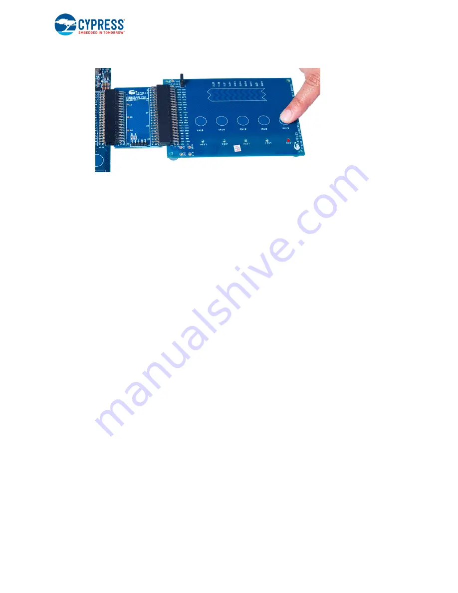
Connect the CapSense Linear Slider Module to connector J2 of the PSoC CapSense Expansion
Board.
■
Connect jumper J2 on the CapSense Linear Slider Module to short SHIELD and SHLD.
■
For the PSoC Development Kit
❐
Connect J1 of the PSoC CapSense Expansion Board Kit to port A of the development kit.
❐
Connect the LCD to P18 and place jumper J12 in the ON position to power on the LCD.


