3
6. OPERATION CONTROLS AND FUNCTIONS
6.1 Front Panel
IP
B
HDMI OUT B
HDMI OUT A
IP
1
2
PORT
A
CAM 2
SDI
HDMI
VGA
CVBS
1
2
CAM 1
SDI
HDMI
VGA
CVBS
RS-232
TX RX
TX RX
SERVICE
DC 24V
GROUP SELECT
LINK
2
1
3
4
5
7 8 9
10
6
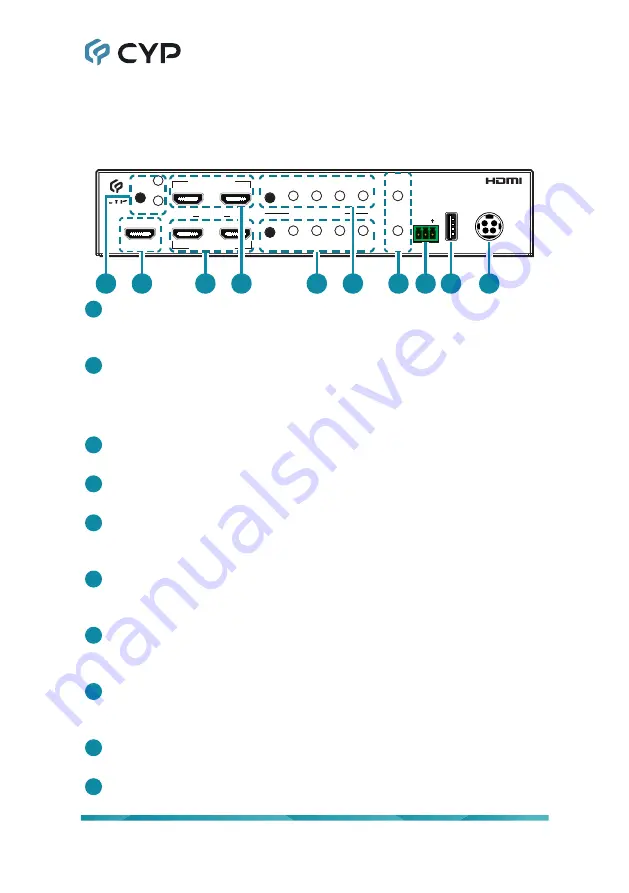
1
IP A/B Button & LEDs:
Press this button to toggle between monitoring
HDMI output A or B on the IP output. The LED will illuminate to indicate
which output is currently being monitored by the IP output.
2
IP HDMI Output Port:
Connect to an HDMI TV, monitor, amplifier or
other HDMI receiving device for digital video and audio output.
Note: This output port is primarily intended for monitoring and will
typically be connected to a IP streaming or recording device.
3
HDMI OUT A Ports 1 & 2:
Connect to HDMI TVs, monitors, or amplifiers
for digital video and audio output.
4
HDMI OUT B Ports 1 & 2:
Connect to HDMI TVs, monitors, or amplifiers
for digital video and audio output.
5
GROUP SELECT 1 Button and LEDs:
Press this button to sequentially
switch through the available sources to display in the “Group 1” window.
The LED will illuminate to indicate which source is currently selected.
6
GROUP SELECT 2 Button and LEDs:
Press this button to sequentially
switch through the available sources to display in the “Group 2” window.
The LED will illuminate to indicate which source is currently selected.
7
CAM 1 & 2
Link LEDs:
These LEDs will illuminate to indicate that a live
source has been detected on the associated input port. When no source
is detected the LED will remain off.
8
RS-232 3-pin Terminal Block:
Connect directly to a PC, laptop, or
other serial control device with a 3-pin adapter cable to send RS-232
commands to control the unit.
9
SERVICE USB 2.0 Port:
This port is reserved for firmware update use
only.
10
DC 24V Port:
Plug the 24V DC power adapter into this port and connect
it to an AC wall outlet for power.


