I.B. 29C891B
Page 42
Effective 11/98
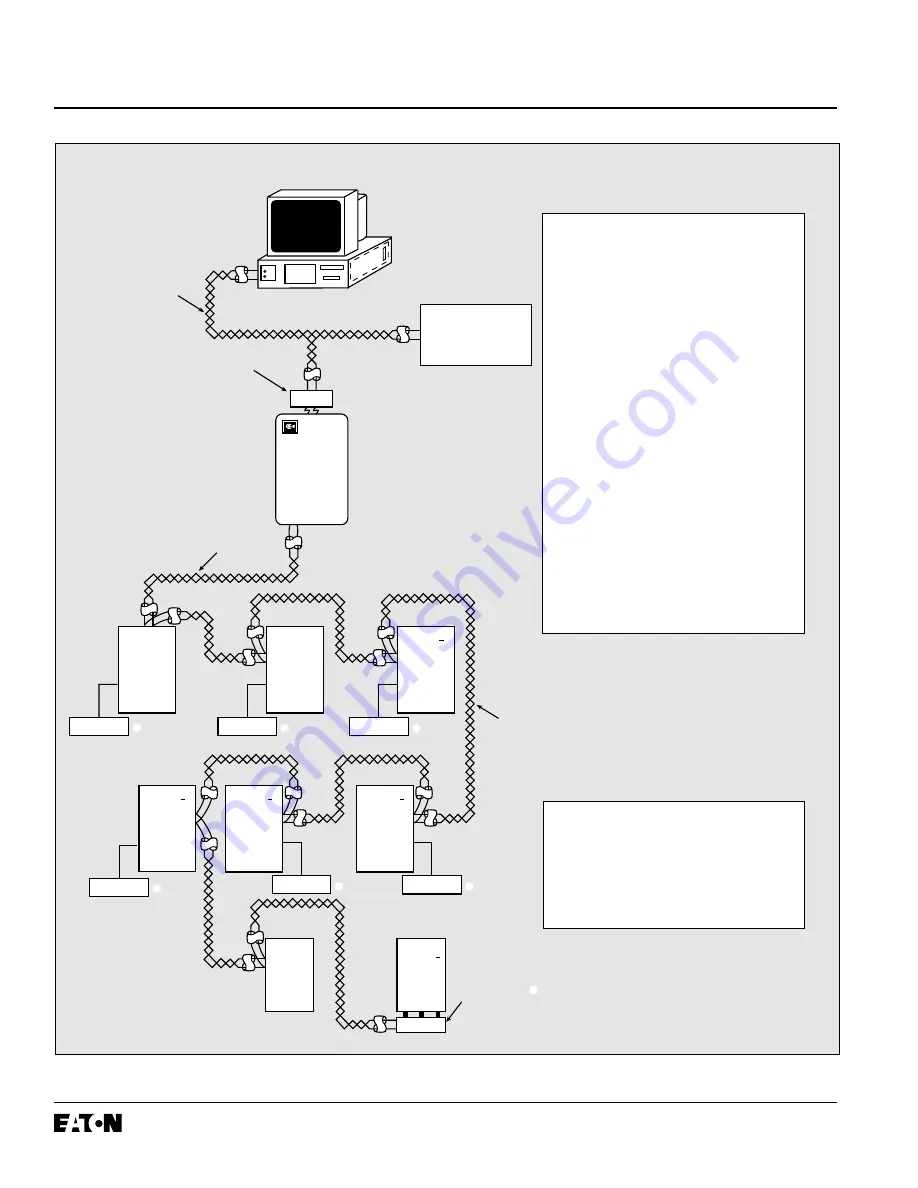
Figure 4-1 Typical Network Wiring Diagram
Master
Computer
Breaker
Interface
Module
Shielded
Twisted
Pair
SPB
Circuit
Breaker
with
OPTIM
DSII
Circuit
Breaker
with
OPTIM
Series C
R-Frame
MCCB
with
OPTIM
To Other IMPACC
Compatible Devices
PONI
OPTIMizer
Series C
N-Frame
MCCB
with
OPTIM
Series C
L-Frame
MCCB
with
OPTIM
Circuit
Breaker
with
RMS 810
or 910
Series C
F-Frame
MCCB
ES
IQ Energy Sentinel
Shielded
Twisted
Pair
PONI Module
(Required for IMPACC
Network Communications
to Master Computer)
Shielded
Twisted
Pair
➁ ➂
➃
OPTIMizer
➀
➀
OPTIMizer
➀
OPTIMizer
➀
OPTIMizer
➀
Series C
K-Frame
MCCB
with
OPTIM
OPTIMizer
➀
➀
For network interconnection cable,
use Belden 9463 or Cutler-Hammer
IMPCABLE.
➁
When interconnecting devices, tie
shield drain wires together for shield
path continuity.
➂
Connect the shield path to a solid
earth ground at one point only.
➃
On last device in network, tape shield
drain wire back upon cable.
➄
Use a 1/2 watt carbon or metal film
resistor at each end of the network
as an end of line termination resistor
(EOLTR). EOLTR should be 100 ohms
for 9600 baud communication rate
networks or 150 ohms for 1200 baud
communication rate networks.
➅
Network interconnection to computer
requires use of an IMPACC master
(CONI or MINT).
➆
Devices without built-in communica-
tions require network interface module
(PONI).
For detailed network wiring specifications,
call the automatic fax retrieval system
(FRED) at 412/494-3745 and request
document 17513 or contact the
Advanced Products Support Center.
Refer to the paragraph entitled
“Technical Assistance” in this document.
Содержание Digitrip OPTIM 1050
Страница 7: ......


