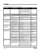
Breaker trips on ground
There actually is a ground fault
Find the location of the fault and remove it.
N.A.
fault.
On four wire systems the neutral
Check the connections at terminals at D6 and D7
Table A.1
current sensor may not have the
on RD and SPB breakers or 19 and 20 on DSII
Wiring Diagrams
correct ratio or be properly con-
breakers. Check that the neutral current sensor
nected.
ratio matches the breaker. Check that connec-
tions from the neutral current sensor to the
breaker are not reversed. Check that the short-
ing straps on the four point ground fault term-
inal block on RD and SPB breakers are connected
D5 - D6 and D7 - D8.
Trip unit may be the problem.
Replace trip unit
Para. 5-3
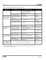
Breaker trips too rapidly
Connections from C4 to C5 and/or
Add connections
Table A.1
on ground fault or short
D9 to D10 missing on RD or SPB
Wiring Diagrams
delay (zone selective
breakers.
interlocking not used).
Connections from Z2 to Z3 and/or Z4
Add connections
Table A.1
to Z5 missing on DSII breakers.
Wiring Diagrams
Trip unit settings are not correct
Change settings
I.B. 29C892, Section 3
or
I.B. 29C893, Section 4
Trip unit may be the problem.
Replace trip unit
Para. 5-3
Breaker trips too rapidly
Powered thermal memory can cause
If powered thermal memory is not required,
I.B. 29C892, Para. 3-6
on long delay.
breaker to trip too soon.
turn it off with the OPTIMizer.
Trip unit settings are not correct
Change settings
I.B. 29C892, Section 3
or
I.B. 29C893, Section 4
Trip unit may be the problem.
Replace trip unit
Para. 5-3
Zone selective interlocking
on ground fault and/or
See directions for checking zone selective interlocking
Appendix B
short delay does not work.
Communication over
Address incorrect
Verify both the IMPACC address and trip unit
Review Section 3
IMPACC is not working.
address are properly setup.
of IB 29C890
(Direct with BIM not
involved)
No auxiliary power
If possible, open breaker or reduce breaker
Symptom: “Unit
current to <20% of frame rating. Then check
Status LED is not
that unit status LED is blinking. If not, see first
blinking.”
symptom in this portion of the table.
Open INCOM connection
Check connections at terminals C11 and C12 on
Table A.1
(Continues on next page)
RD and SPB breakers or C6 and C7 on DSII
Wiring Diagrams
I.B. 29C891B
Page 50
Effective 11/98
Table 5.1 Troubleshooting Guide (continued from previous page)
Symptom
Probable Cause
Possible Solution(s)
References
Содержание Digitrip OPTIM 1050
Страница 7: ......


