I.B. 29C891B
Page 40
Effective 11/98
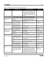
4-3.1 BEFORE POWER APPLICATION
STARTUP PROCEDURES MUST BE PERFORMED
BY QUALIFIED PERSONNEL WHO ARE FAMILIAR
WITH DIGITRIP OPTIM TRIP UNITS, THE LOW VOLT-
AGE CIRCUIT BREAKERS IN WHICH THEY ARE
APPLIED, AND ALL OTHER ASSOCIATED ELECTRI-
CAL AND/OR MECHANICAL EQUIPMENT. FAILURE
TO OBSERVE THIS WARNING COULD RESULT IN
PERSONAL INJURY, DEATH AND/OR EQUIPMENT
DAMAGE.
After all installation wiring is complete and before power
is applied to any equipment, perform the following steps:
Step 1:
Verify that all wiring is correct as shown on the
applicable wiring diagrams and/or wiring plan
drawings.
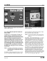
Step 2:
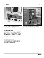
Remove and discard the factory default set-
tings label covering the programming port on
each trip unit.
Step 3:
Verify that a correct rating plug is securely
installed in each trip unit.
Notice:
Mechanical rejection means will prevent the
installation of a rating plug in a trip unit for
which it was not intended.
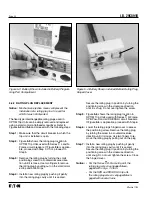
Step 4:
Press the battery test/check pushbutton. The
associated green LED should light. Refer to
paragraph 5-4.1 for specific assistance.
Step 5:
Use the OPTIMizer Hand Held Programmer to
assign unique device addresses and select
baud rates. Refer to the OPTIMizer Hand Held
Programmer Instruction Book 29C892 for spe-
cific assistance.
Notice:
• For applications with Breaker Interface
Modules
- the acceptable address ranges for trip units
are 1-32 (HEXADECIMAL).
• For applications with a remote PC and no
Breaker Interface Modules present
- the acceptable address ranges for trip units
are 1-FFE (HEXADECIMAL).
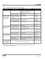
Step 6:
Use the OPTIMizer Hand Held Programmer to
check and adjust, if necessary, trip unit pickup
SECTION 4: STARTUP AND TESTING
4-1 INTRODUCTION
This section addresses those procedures associated
with the startup and testing of installed Digitrip OPTIM
Trip Units. As a minimum, the OPTIMizer Hand Held
Programmer Instruction Book 29C892 along with this
instruction book will be required to complete the system
setup, program the trip unit, and functionally test the trip
unit and circuit breaker.
4-2 WIRING
This section references wiring diagrams that are associ-
ated with specific circuit breakers and their installed
Digitrip OPTIM Trip Units. All wiring must conform to
applicable federal, state and local codes.
4-2.1 WIRING DIAGRAMS
Specific wiring diagrams (connection diagrams) present
all the required direct connections associated with a par-
ticular circuit breaker type with an installed Digitrip
OPTIM Trip Unit. Wiring diagrams are identified by cir-
cuit breaker type in Appendix A. These wiring diagrams
are required to create an accurate wiring plan drawing.
4-2.2 WIRING PLAN DRAWING
External wiring associated with a circuit breaker and its
installed Digitrip OPTIM Trip Unit must follow a suitable
wiring plan drawing. The phrase “wiring plan drawing”
refers to the drawing or drawings made for a specific
application. All electrical connections between the circuit
breaker and external equipment are described. This
drawing is the responsibility of the OEM or user.
4-2.3 NETWORK WIRING DIAGRAM
A network wiring diagram would also be helpful for sub-
network and network systems. This diagram is the
responsibility of the OEM or user. Refer to Figure
4-1
to
review a typical network wiring diagram.
4-3 INITIAL STARTUP
This information is intended to be used when applying
control power to a system, including the trip units. It is
especially important during the first power application.
WARNING
Содержание Digitrip OPTIM 1050
Страница 7: ......


