background image

MANUAL CONTENTS

In addition to the Introduction which includes a description of the explanatory notes used in the manual, gen-
eral
safety information, how to unpack the printer and a brief description of the printer including its basic features,
this manual is organized as follows:
Chapter 1: Contains the information required for correct printer installation and its proper use
Chapter 2: Contains information on interface speci

fi

 cations

Chapter 3: Contains a description of the printer command set
Chapter 4: Contains Technical Speci

fi

 cations of the printer

Chapter 5: Contains the character sets (fonts) used by the printer

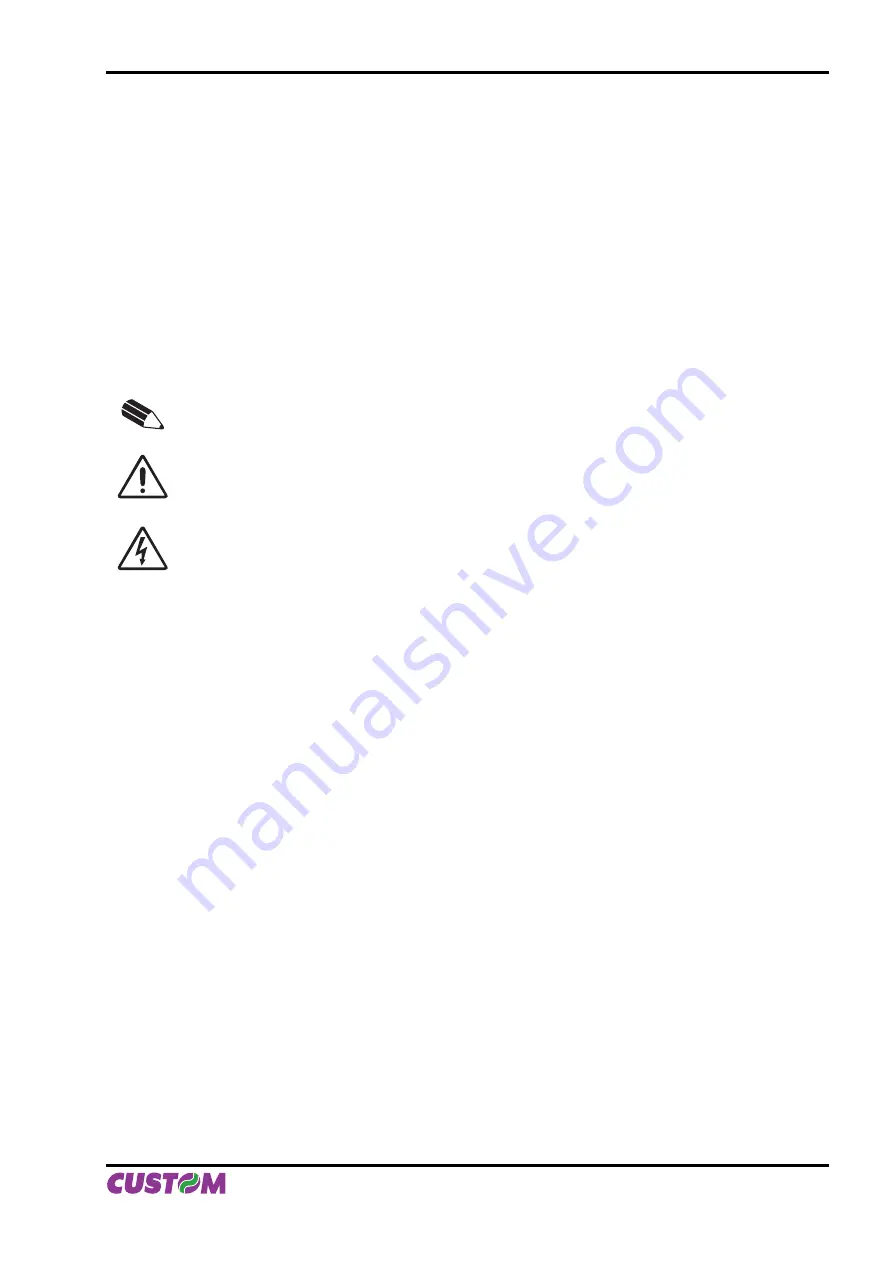
EXPLANATORY NOTES USED IN THIS MANUAL

N.B.

Gives important information or suggestions relative to the use of the printer.

WARNING

Information marked with this symbol must be carefully followed to guard against damaging the
printer.

DANGER

Information marked with this symbol must be carefully followed to guard against operator injury 
or damage..

GENERAL SAFETY INFORMATION

Read and keep the instructions which follow.

• 

Follow all warnings and instructions indicated on the printer.

• 

Before cleaning the printer, disconnect the power supply.

• 

Clean the printer with a damp cloth. Do not use liquid or spray products.

• 

Do not operate the printer near water.

• 

Do not use the printer on unstable surfaces that might cause it to fall and be seriously damaged.

• 

Only use the printer on hard surfaces and in environments that guarantee proper ventilation.

• 

Make sure the printer is placed in such a way as to avoid damage to its wiring.

• 

Use the type of electrical power supply indicated on the printer label. If in doubt, contact your retailer.

• 

Do not block the ventilation openings.

• 

Do not introduce foreign objects of any kind into the printer as this could cause a short circuit or damage 

• 

parts that could jeopardize printer functioning.
Do not spill liquids onto the printer.

• 

Do not carry out technical operations on the printer, with the exception of the scheduled maintenance 

• 

procedures speci

fi

 cally indicated in the user manual.

Disconnect the printer from the electricity supply and have it repaired by a specialized technician when:

• 

The feed connector has been damaged.

A. 

Liquid has seeped inside the printer.

B. 

The printer has been exposed to rain or water.

C. 

The printer is not functioning normally despite the fact that all instructions in the users 

D. 

manual have been followed.
The printer has been dropped and its outer casing damaged.

E. 

Printer performance is poor.

F. 

The printer is not functioning.

G. 

INTRODUCTION

User Manual

  VKP112  1

Содержание VKP112

Страница 1: ...OEM USER MANUAL VKP112 VKP112 Command Reference DOMC 0001e ...

Страница 2: ...the manual is used Information regarding any errors found in it or suggestions on how it could be improved are appreciated Since products are subject to continuous check and improvement CUSTOM ENGINEERING SPA reserves the right to make changes in information contained in this manual without prior notification Copyright 2009 CUSTOM ENGINEERING S p a Italy CUSTOM ENGINEERING S p A Str Berettine 2 43...

Страница 3: ...PRINTER COMPONENTS A Front external view 1 Printing mechanism 2 Cutter 3 Paper mouth 4 Paper out 5 Ejector unit mechanism 6 Printing mechanism motor 6 5 1 2 4 3 Fig 1 User Manual VKP112 ...

Страница 4: ...5 Near paper end sensor 6 LINE FEED key 7 FORM FEED key 8 POWER ON Led 9 STATUS Led 10 PAPER LOW Led 11 SERIAL interface connector 12 USB interface connector 13 Near paper end connector 14 Power supply connector 15 Unblocking lever for printing head 16 Unblocking lever for ejector unit 15 16 14 12 11 2 1 3 4 5 6 7 8 9 10 13 Fig 2 VKP112 User Manual ...

Страница 5: ... 5 Near paper end sensor 6 LINE FEED key 7 FORM FEED key 8 POWER ON Led 9 STATUS Led 10 PAPER LOW Led 11 CENTRONICS parallel interface connector 12 Near paper end connector 13 Power supply connector 14 Unblocking lever for printing head 15 Unblocking lever for ejector unit 15 16 14 12 11 2 1 3 4 5 6 7 8 9 10 13 Fig 3 User Manual VKP112 ...

Страница 6: ...ter components described previously see fig 1 are grouped as follows see fig 2 1 Ejector unit 2 Metal chassis 3 Paper roll holder unit 4 Electronic board 5 Printing mechanism 5 4 1 2 3 Fig 4 VKP112 User Manual ...

Страница 7: ...roll holder support 1 8 1 5 4 Changing the paper roll 1 10 1 5 5 Cleaning the printer 1 12 1 5 6 Ticket specifications 1 13 2 INTERFACES 2 1 RS232 SERIAL INTERFACE 2 1 2 2 USB INTERFACE 2 3 2 3 CENTRONICS PARALLEL INTERFACE 2 4 3 TECHNICAL SPECIFICATION 3 1 TECHNICAL SPECIFICATIONS 3 1 3 2 DIMENSIONS 3 3 3 2 1 VKP112 printer with paper roll holder support 3 3 4 CHARACTER SETS 4 1 CHARACTER SETS 4 ...

Страница 8: ...Blank page TABLE OF CONTENTS ii VKP112 User Manual ...

Страница 9: ...nter with a damp cloth Do not use liquid or spray products Do not operate the printer near water Do not use the printer on unstable surfaces that might cause it to fall and be seriously damaged Only use the printer on hard surfaces and in environments that guarantee proper ventilation Make sure the printer is placed in such a way as to avoid damage to its wiring Use the type of electrical power su...

Страница 10: ...gh resolution thermal printed tickets ideal for use in information and multimedia kiosks self service machines no queue systems parking areas gaming machines and toll receipt machines Two ticket presentation systems are available on the VKP112 printer Motor driven dispenser with sensors on the dispenser that holds the ticket while it is being printed and then delivers it once it has been cut Ideal...

Страница 11: ...NE FEED key is pressed the printer advances the paper so that it may be inserted manually in the printing mechanism During power up if the LINE FEED key is held down the printer will perform the FONT TEST routine If it has the version with chinese simplified font GB2312 option 0104 at the end of the FONT TEST is printed all characters set about 7000 FORM FEED key If the FORM FEED key is enabled wh...

Страница 12: ...ter the beginning of the font test press at the same time the LINE FEED key and the FORM FEED key At the end of the font test the printer begin the notch threshold autocalibration The Power On LED green indicates that the printer is on The Paper Low LED red indicates that the paper is about to run out The Status LED yellow indicates printer status the check is made on line Given in the table 1 are...

Страница 13: ... equipped with a male 90 mobile screw pitch 5 08mm terminal J5 The signals on the power supply connector pins are as follows PIN No SIGNAL 1 GND 2 24 Vcc power supply WARNING Respect power supply polarity Fig 1 1 Tab 1 1 J5 1 1 INSTALLATION AND USE User Manual VKP112 1 1 ...

Страница 14: ...URE C 22 5 PAPER PRINTED cm 9860 CUT COUNTER 604 POWER ON COUNTER 135 Printer emulation CUSTOM TPT Baud Rate 3 9600 bps Data length 3 8 bits chr Parity 3 None Handshaking 3 Xon Xoff Autofeed CR Disabled Panel key Enabled Print Mode Normal Height Mode x 1 Width Mode x 1 Justification Left Character set U S A Font Dimension 16x24 28 col Speed Quality Normal Current Normal Paper autoload Enabled Rese...

Страница 15: ...t are the same models for example two TPTCM60 U 5 NOTE This parameter is displayed if the printer has an USB interface The Status Monitor is an additional printing driver component that allows the printer status monitoring It must be enabled only if it was installed the Status Monitor specific driver 1 3 CONFIGURATION This printer permits the configuration of default parameters The printer s confi...

Страница 16: ... When the FORM FEED key is pressed the printer enters the parameter entry mode 1 4 HEXADECIMAL DUMP This function is used to diagnose the characters received through the communication port the characters are printed out both as hexadecimal codes and ASCII codes Once the self test routine has finished the printer enters Hexadecimal Dump mode The printer remains in standby until a key is pressed or ...

Страница 17: ...eration inside the printer immediately after printing because the head and motor tend to become very hot 1 5 1 Open the printer To open the printer proceed as follows turn down the unblocking lever and lift up the ejector unit to the maximum opening position see fig 1 5 push down the rubber feet and unhook the printing mechanism see fig 1 6 NOTE After each maintenance operation is recommended to c...

Страница 18: ...see fig 1 7 e Remove possible scraps of paper see fig 1 8 Open the printer see previous paragraphs and remove possible scraps of paper near the cutter see fig 1 9 and under printing mechanism see fig 1 10 1 2 Fig 1 7 Fig 1 8 Fig 1 6 1 INSTALLATION AND USE 1 6 VKP112 User Manual ...

Страница 19: ...3 4 Fig 1 9 Fig 1 10 1 INSTALLATION AND USE User Manual VKP112 1 7 ...

Страница 20: ...ow P4 and lower P5 To fastening the paper roll holder support proceed as follows Bring up the paper roll holder support Move it until three of the radial holes coincide with three of the holes on the printer body Fasten the paper roll holder support with the printer body by the three M4x8 fastening screws supplied P1 P2 Fig 1 11 Fig 1 12 1 INSTALLATION AND USE 1 8 VKP112 User Manual ...

Страница 21: ...P3 P4 P5 Fig 1 13 Fig 1 14 Fig 1 15 1 INSTALLATION AND USE User Manual VKP112 1 9 ...

Страница 22: ...atically see fig 1 17 2 2 VRRR 1 PAPER AUTOLOAD NOT ENABLED Position the paper roll so that it unrolls correctly as shown in fig 1 18 raise the print head by lifting the 1 lever in the direction indicated by the arrow insert the end of the paper roll into the infeed slot and have it pass beyond the print head Lower the head lever see fig 1 19 2 Press the LINE FEED key so that the paper will feed a...

Страница 23: ...1 3 VRRR 2 Fig 1 18 Fig 1 19 Fig 1 20 1 INSTALLATION AND USE User Manual VKP112 1 11 ...

Страница 24: ... fig 1 21 1 5 5 Cleaning the printer The user is responsible for cleaning the printer case To clean the unit use compressed air or a soft cloth Do not use alcohol solvents or stiff brushes Alcohol solvent Fig 1 21 Fig 1 22 1 INSTALLATION AND USE 1 12 VKP112 User Manual ...

Страница 25: ... side If required the printer can do the notch sensor autocalibration so the sensor can adjust to different kind of paper and always identify the black notch On fig 1 6 and 1 7 there are notch position and dimensions on the 60 mm and 112 mm width thermal paper Direction of paper advance Cutting line Printing line Photocell axis Black notch NON thermal side 112 50 1 1 33 8 1 1 9 1 0 5 1 0 Fig 1 23 ...

Страница 26: ...Blank page 1 INSTALLATION AND USE 1 14 VKP112 User Manual ...

Страница 27: ...D Data Carrier detect Printer ON active at level RS232 high 2 TXD OUT RXD Receive data Serial output from Host 3 RXD IN TXD Transmit data Serial data input towards Host 4 N C N C Not connected 5 GND GND Ground signal 6 DSR OUT DSR Data Set Ready Printer on and operating active at RS232 level high 7 N C N C Not connected 8 RTS OUT CTS Clear to send Ready to receive data active at RS232 high level 9...

Страница 28: ...ow examples of connections between the printer and the Personal Computer using 25 and 9 pin female connectors DCD DCD RXD TXD TXD RXD SIGNAL GND SIGNAL GND DSR DSR CTS CTS Printer PC Fig 2 2 2 INTERFACES 2 2 VKP112 User Manual ...

Страница 29: ...he following specifications Communication speed 12 Mbit sec Receptacle series B type connector Refer to the table below for the connector pin signals and connection to a device PIN SIGNAL DESCRIPTION 1 VBUS N C 2 D Data 3 D Data 4 GND Ground signal Shell Shield Shield Tab 2 2 Fig 2 3 2 INTERFACES User Manual VKP112 2 3 ...

Страница 30: ...be Strobe input 2 D0 Data input bit 0 3 D1 Data input bit 1 4 D2 Data input bit 2 5 D3 Data input bit 3 6 D4 Data input bit 4 7 D5 Data input bit 5 8 D6 Data input bit 6 9 D7 Data input bit 7 10 ACK Acknowledge 11 BUSY Occupato 12 PE Paper end 13 SELECT Select Ticket presence Near paper end 14 N C Not connected 15 FAULT Fault Ticket presence Near paper end 16 RESET Printer reset 17 GND GND 18 N C ...

Страница 31: ...g of the Centronics parallel port The signal Ticket Presence is high if the ticket is present on the mouth of exit the signal Near paper end is high when the RED LED has turned on For the parallel connector the connection between printer and Personal Computer must be made with a 25 pin to pin connector 2 INTERFACES User Manual VKP112 2 5 ...

Страница 32: ...Blank page 2 INTERFACES 2 6 VKP112 User Manual ...

Страница 33: ...ernational Graphic memory 3 logos 832 x 314 each Weight 2600 gr PAPER SPECIFICATIONS Type of paper Thermal rolls heat sensitive side on outside of roll Recommended types of paper 2 from 58 g m2 to 80 g m2 KANZAN Paper thickness from 0 063 mm to 0 080 mm Paper roll size 111 5 mm 0 5 mm External roll diameter max 130 mm 3 max 160 mm 4 Internal roll core diameter 25 mm 1 mm Core thickness 2 mm 1 mm C...

Страница 34: ...1 x 6 Double height and width 3 4 x 6 2 4 x 6 2 x 6 Quadruple height 6 8 x 3 4 8 x 3 4 x 3 Quadruple width 1 7 x 12 1 7 x 12 1 x 12 Quadruple height and width 6 8 x 12 4 8 x 12 4 x 12 CUSTOM TPT EMULATION Number of columns 34 52 104 Printing speed Lines sec 12 5 16 7 25 Characters sec 425 868 2600 Characters L x H mm Normal 3 x 4 2 x 3 1 x 2 Double height 6 x 4 4 x 3 2 x 2 Double width 3 x 8 2 x 6...

Страница 35: ...lowing figures shows the dimension of the VKP112 printer with the paper roll holder support on 5 different positions upper P1 45 degrees up P2 rear P3 45 degrees low P4 and lower P5 and with the ejec tor unit wide opened Fig 3 1 3 TECHNICAL SPECIFICATIONS User Manual VKP112 3 3 ...

Страница 36: ... Fig 3 2 Fig 3 3 Fig 3 4 3 TECHNICAL SPECIFICATIONS 3 4 VKP112 User Manual ...

Страница 37: ... Fig 3 5 Fig 3 6 3 TECHNICAL SPECIFICATIONS User Manual VKP112 3 5 ...

Страница 38: ...Blank page 3 TECHNICAL SPECIFICATIONS 3 6 VKP112 User Manual ...

Страница 39: ...4 characters each with 224 characters two font for every emulation ESC POS Emulation PC437 USA Standard Europe FONT 14X24 FONT 10X24 FONT 8X24 Custom TPT Emulation FONT 16X24 FONT 24X32 FONT 8X16 Fig 4 1 Fig 4 2 4 CHARACTER SETS User Manual VKP112 4 1 ...

Страница 40: ...t has the version with chinese simplified font GB2312 option 0104 at the end of the FONT TEST is printed all characters set about 7000 as shown in the fig 4 3 Fig 4 3 4 CHARACTER SETS 4 2 VKP112 User Manual ...

Страница 41: ...x symbol identifies the character to address 1st byte Range 161 n 169 A1 A9 176 n 247 B0 F7 2nd byte Range 160 m 255 A0 FF Address A1E8 Address B0C5 Address F7FF 0 1 2 3 4 5 6 7 8 9 A B C D E F A0 B0 C0 D0 E0 F0 0 1 2 3 4 5 6 7 8 9 A B C D E F A0 B0 C0 D0 E0 F0 0 0 1 1 2 2 3 3 4 4 5 5 6 6 7 7 8 8 9 9 A A B B C C D D E E F F A0 A0 B0 B0 C0 C0 D0 D0 E0 E0 F0 F0 A1 A9 B0 F7 X X X Fig 4 4 4 CHARACTER ...

Страница 42: ...Blank page 4 CHARACTER SETS 4 4 VKP112 User Manual ...

Страница 43: ...ply 24V 150W Input specifications Input voltage 115 230 V Current 0 6 3 A Input frequency 47 63 Hz Output specifications Output voltage 24 V Output current min max 0 6 5 A Efficiency min 78 Environmental conditions Operating temperature 0 70 C Humidity 20 85 Rh w o condensation Storage temperature Humidity 10 75 C 10 95 Rh w o condensation Protection devices Shortcircuit overload Fig A 1 APPENDIX ...

Страница 44: ...1 Turn the printer upside down the operations described below are to be performed on the ejector unit see fig A 2 2 Unscrew the two nuts A and washers B as shown in fig A 3 and pulling in the direction indicated by the arrow remove the paper slot C on the ejector unit N B Put the nuts and washers aside for the operations that follow A B C Fig A 2 Fig A 3 EJECTOR UNIT APPENDIX A ACCESSORIES AND SPA...

Страница 45: ...in fig A 4 and attach it to the inserts using the two nuts A and washers B removed previously A B C A 2 SPARE PARTS A 2 1 Supplies RCT112x95 25MM Thermal paper roll 112mm Fig A 4 APPENDIX A ACCESSORIES AND SPARE PARTS User Manual VKP112 A 3 ...

Страница 46: ...Blank page APPENDIX A ACCESSORIES AND SPARE PARTS A 4 VKP112 User Manual ...

Страница 47: ......

Страница 48: ...r DOME VKP112 Rev 1 15 www custom biz CUSTOM ENGINEERING SPA World Headquarters Via Berettine 2 43010 Fontevivo Parma ITALY Tel 39 0521 680111 Fax 39 0521 610701 info custom biz www custom biz All rigths reserved ...

Отзывы: