background image

747 Omni™ Bender

CURRENT TOOLS • P. O. BOX 17026 GREENVILLE, SC  29606

800.230.5421 or 864.721.4230 • FAX 864.721.4232

www.currenttools.com

Operating, Maintenance, Safety

and Parts Manual

 05/2018

This manual is free of charge. All personnel who operate or  

service this Bender should have a copy of this manual and read and 

understand its contents. To request a copy, call, write to the address 

below or visit our website at www.currenttools.com.

Read and understand this material before 

operating or servicing this Bender. Failure to 

understand how to safely operate and service 

this unit may result in serious injury or death.

CONDUIT BENDER

91FF

Содержание Omni 747

Страница 1: ... All personnel who operate or service this Bender should have a copy of this manual and read and understand its contents To request a copy call write to the address below or visit our website at www currenttools com Read and understand this material before operating or servicing this Bender Failure to understand how to safely operate and service this unit may result in serious injury or death COND...

Страница 2: ... Stop Switch 14 15 Support Roller Return Spring 16 1 2 to 11 4 Bending Instructions 17 18 11 2 and 2 Bending Instructions 19 23 1 2 to 2 Bending Instructions PVC Coated Rigid 24 25 Bend Degree Pointer Adjustment 26 Stub Up Bending Information 27 Springback Charts 28 Offset Bending Information and Charts 29 30 Maintenance 31 33 Troubleshooting 34 35 Exploded Views and Parts List 36 45 Electrical Sy...

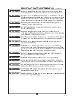
Страница 3: ...mmediate hazards which if not avoided WILL result in serious personal injury or death DANGER THIS SAFETY SYMBOL is used to call your attention to instructions that concern your personal safety It means ATTENTION BE AWARE THIS IS AN IMPORTANT SAFETY INSTRUCTION Read understand and follow these safety instructions Failure to follow these safety instructions may result in injury or death Safety Alert...

Страница 4: ...educe the risk of unintentional starting ALWAYS use 12 gauge extension cords that have three prong grounding type plugs and three hole receptacles that accept the bender s plug DO NOT use an adapter NEVER use an extension cord longer than 100 feet NEVER use a damaged extension cord ALWAYS disconnect power to the bender before servicing or changing shoes attachments or supports and when not in use ...

Страница 5: ...parel Do not wear loose clothing gloves neckties rings bracelets or other jewelry which may get caught in moving parts Non slip footwear is recommended Wear protective hair covering to contain long hair ALWAYS use appropriate shoe groove and roller support for the type and size conduit to be bent ALWAYS keep conduit under control when unloading Some accessories and components exceed 50 lbs and wil...

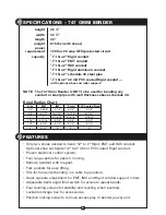
Страница 6: ...s 1 2 to 2 40 mil PVC coated Rigid conduit Proven electrical control system Four large casters for ease in moving Remote pendant with magnet Fork pockets for easy lifting Tilts for horizontal bending in a table top position Quick squeeze adjustment for EMT IMC and Rigid conduit support rollers Adjustable bend angle limit switch for accurate repeat bends Four leveling screws for stability and level...

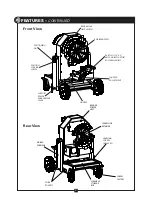
Страница 7: ...WL BUILT IN 1 1 2 2 EMT AND IMC SUPPORT ROLLER ASSEMBLY SQUEEZE ADJUSTMENT HANDLE SUPPORT ROLLER ENGAGEMENT LEVER POSITION LOCKING SCREW POSITIONING PIN BENDER POWER UNIT SPARE SHOE RETAINER LEVELING SCREW 4 PLACES SWIVEL CASTERS LOCKABLE STORAGE BOX FORK POCKETS MOBILE CARRIAGE ...

Страница 8: ...trician Improper connection of the equipment grounding conductor can result in risk of electric shock The conductor with insulation having an outer surface that is green with or without yellow stripes is the equipment grounding conductor If repair or replacement of the electric cord or plug is necessary do not connect the equipment grounding conductor to a live terminal Check with a qualified elec...

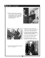
Страница 9: ...ded positioning pin will snap into place when you reach the horizontal position 4 To remove excess play tighten the position locking screw ALWAYS rotate the bender power unit into the horizontal position before lifting rolling or any type of transporting WARNING Positioning Pin Position Locking Screw To lift Use the two fork pockets on either side of the unit to lift with a forklift To roll Push a...

Страница 10: ...eveling screws to hold the bender in place To level the bender if needed Lower the remaining two leveling screws and adjust as required The 747 Omni Bender has two bending positions horizontal and vertical If desired rotate the bender power unit into the vertical position 1 Unscrew the position locking screw until it clears the bender power unit ...

Страница 11: ...positioning pin 3 While continuing to hold the handle rotate the bender power unit into the vertical position 4 The spring loaded positioning pin will snap into place when you reach the vertical position 5 To remove excess play tighten the position locking screw 6 Connect the power cord to a 20 amp GFCI protected circuit 7 Place the circuit breaker switch in the on position ...

Страница 12: ... Press down on the spring loaded retainer pawls to remove both shoes see photo at right 2 Place the shoe you are not using onto the spare shoe tube located on the rear of the bender 3 Next you must rotate the bend degree pointer for the size shoe you have chosen to the minus ten degree 10 position To do this set the switch on the pendant to the UNLOAD position Then press the JOG button and rotate ...

Страница 13: ...elow 4 Place the shoe on the bender so that the hook for the type conduit to be bent is at approximately the 6 o clock position Note that the bending shoe hooks are color coded The blue hooks are for Rigid and IMC conduit and the silver hooks are for EMT conduit NOTE The bending shoe should be pushed completely onto the nose of the bender to allow the retaining pawl to secure the bending shoe NOTE...

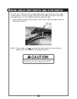
Страница 14: ...t from approximately five degrees 5 to one hundred and five degrees 105 1 To set the Bend Angle Limit Switch slide to the desired degree of bend See photo below NOTE The pointers will only activate the bend angle limit switch when operating in the clockwise bending direction DO NOT bend over 105 Doing so will cause the hook on the other side of the shoe to collide with the conduit CAUTION ...

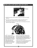
Страница 15: ...cated behind the face plate and main sprocket of the bender and is designed to stop the bender shoe from turning if the pointer does not activate the Bend Angle Limit Switch thus avoiding damage to the shoe hook and roller assembly NOTE If the stop switch activates and stops the bending shoe from turning in the bend direction change the Bend Unload switch to the Unload position and press jog butto...

Страница 16: ... See Figure A1 The return spring is designed to return the support rollers to the down position See Figure A2 after a bend is completed Returning the support roller assembly to the down position after a bend will help prevent the bender shoe hooks from contacting the rollers when the rollers are not in use Return Spring Support roller assembly shown in raised bending position Support roller assemb...

Страница 17: ...e as described in the shoe set up section on pages 12 and 13 2 Next install the 1 2 thru 11 4 pin on roller support see photo below 1 2 thru 11 4 EMT IMC and Rigid conduit all use the pin on 4 roller support Part 747 972 Attach the pin on roller support as shown below PIN ON ROLLER SUPPORT PIN ...

Страница 18: ...oe groove and into the hook The bending mark should be at the front outside edge of the hook See figure below 6 After consulting the springback chart found on page 28 in this manual or on the bender instruction decal on the top of each bender slide the bend angle limit switch to the desired degree NOTE If you do not want to use the bend angle limit switch slide it clockwise as far as possible abou...

Страница 19: ...the shoe set up section on pages 12 and 13 2 Next install the 11 2 and 2 pin on roller support see photo below Attach the pin on roller support as shown below 11 2 and 2 EMT and IMC use the pin on urethane roller support and the built in support roller system Part 747 33 PIN ON ROLLER SUPPORT PIN PAGE 19 ...

Страница 20: ...an be found on pages 27 30 in this manual or on the bending instruction decal on top of each bender 5 Place conduit into the bender The conduit should slide over the roller support through the shoe groove and into the hook The bending mark should be at the front outside edge of the hook See figure below 6 After consulting the springback chart found on page 28 in this manual or on the bender instru...

Страница 21: ...nd IMC conduits 8 The built in support roller assembly has a squeeze adjustment feature Recommended starting points for the type and size conduit you are bending are shown below Beginning squeeze adjustment settings NOTE For additional squeeze adjustment information refer to item 14 on page 23 Be aware of pinch points when rotating the rollers into position Always wear gloves CAUTION SET HERE FOR ...

Страница 22: ...onduit 11 Keep pressure on the support roller lever and press the Jog button on the pendant The conduit should pull the support roller arm against the stop see photo below As you continue to bend pressure can then be removed from the support roller lever NOTE If the support rollers will not pull against the stop the squeeze adjustment is set too tight Pull the ring on the squeeze adjustment pin an...

Страница 23: ...g of the conduit occurs on EMT or IMC conduit the squeeze adjustment is set too tight Pull the ring on the squeeze adjustment pin and rotate the arm clockwise to the next hole This will REDUCE the squeeze on the conduit If the EMT or IMC conduit wrinkles when bending the squeeze adjustment is set too loose Pull the ring on the squeeze adjustment pin and rotate the arm counter clockwise to the next...

Страница 24: ...es 12 and 13 NOTE The optional PVC Coated Rigid bending shoe Part 2 3200 7 is a single shoe that will bend the full range of PVC Coated Rigid conduit from 1 2 to 2 2 Next install the 1 2 thru 2 pin on roller support Part 2 4300 7 as shown below 1 2 thru 2 PVC Coated Rigid conduit uses the pin on roller support Part 2 4300 7 Attach the pin on roller support as shown below 24 ...

Страница 25: ...ve and into the hook The bending mark should be at the front outside edge of the hook See figure below 6 After consulting the springback chart found on page 28 in this manual or on the bender instruction decal on the top of each bender slide the bend angle limit switch to the desired degree NOTE If you do not want to use the bend angle limit switch slide it clockwise as far as possible about 105 S...

Страница 26: ...wo bolts holding the pointer 3 Move the pointer as desired 4 Re tighten the two bolts POINTER ADJUSTING BOLTS BEND DEGREE POINTER GAP ADJUSTMENT The magnets mounted on the pointer should not need any adjustments The magnets and the bend angle limit switch should never touch and can operate with as much as a 1 2 gap If the pointer gets bent further than 1 2 from the bend angle limit switch the poin...

Страница 27: ... deduct length See page 28 Note that minimum stub length is deduct length plus 2 2 Measure and mark desired stub length on conduit stub length mark Subtract Deduct Length from this mark and make a second mark bending mark See Fig 27a and 27b Place bending mark at front edge of shoe hook See Figure 27c Check Springback Chart A B or C or C1 for springback of desired degree of bend See page 28 Bender...

Страница 28: ... 4 13 5 8 19 33 50 65 95 1 1 2 14 7 8 17 32 49 63 93 2 16 1 8 17 33 48 64 95 Chart C IMC Conduit Conduit Size Deduct Length Springback 15 30 45 60 90 1 2 7 1 2 22 38 54 69 100 3 4 9 20 36 48 66 98 1 11 20 35 52 67 99 1 1 4 13 5 8 18 33 49 65 95 1 1 2 14 7 8 20 35 51 66 98 2 16 1 4 19 35 51 66 97 NOTE Springback figures are approximate Minimum Stub Length Deduct Length plus 2 Chart C1 PVC Coated Ri...

Страница 29: ...nter distance between marks Measure this distance from Mark 2 and place Mark 3 on conduit See Figure 29b 4 Layout of bends is now complete Next place Mark 2 in line with front edge of shoe hook then check springback chart page 28 and make first bend See Figure 29c 5 Rotate conduit 180 degrees Place Mark 3 in line with front edge of shoe hook then check springback chart page 28 and complete second ...

Страница 30: ... 1 16 4 4 3 4 4 3 4 CHART D OFFSET HEIGHT 2 4 6 8 10 12 14 16 18 20 22 30 45 15 MAX CONDUIT SIZE CENTER TO CENTER MAX CONDUIT SIZE CENTER TO CENTER MAX CONDUIT SIZE CENTER TO CENTER 3 4 1 1 2 2 3 4 1 1 2 2 1 1 2 1 1 4 1 1 1 2 2 2 2 2 2 2 2 2 2 2 2 2 2 2 2 2 2 2 2 7 3 4 61 13 16 15 7 16 23 3 16 30 7 8 38 5 8 46 3 8 54 1 16 69 9 16 77 1 4 85 7 5 16 11 15 16 15 15 16 19 15 16 23 15 16 27 15 16 31 15 ...

Страница 31: ...0X Exxon CYLESSTIC TK460 Mobil 600 W Cylinder Oil Shell Sun Gear Oil 7C 2 To inspect FRONT 60 chain tension Remove face plate To adjust loosen hex screw with 3 4 wrench and rotate chain tensioner toward chain as shown until chain moves no more than a total of 1 4 See Figure 31 below Grease chain periodically with a good quality MP grease ALWAYS disconnect power supply before removing any guards or...

Страница 32: ...crews Loosen 8 bolts 4 on top and 4 on bottom that hold the gear box in position To tighten chain move the gear box to the left and re tighten bolts For correct tension chain should deflect approximately 1 8 NOTE Be sure to keep the gear box and motor in line with the bender Grease chain periodically with a good quality MP grease Access to the gearbox sprocket is possible by removing access door a...

Страница 33: ... screws that hold the face plate onto the bender frame To adjust the spring pressure loosen or tighten the 2 hex nuts Item 125 Check the tension by sliding the Bend Angle Limit Switch in the slot Reinstall the face plate 5 Roller Supports We recommend lubrication of the built in support roller system rollers and roller support unit rollers every 6 months Use a good quality MP grease A grease fitti...

Страница 34: ...tactor bad Check contacts and ohm coil for open circuit Replace Bridge rectifier bad Check with ohm meter Replace Switch bad Check with ohm meter Replace Motor bad Check brushes and ohm for open or short armature Replace 4 Motor runs but will not bend Chain from gear box to jack shaft broken Remove cover and visually check for broken parts Replace Bad gear box Motor running but no output through g...

Страница 35: ...imit switch in the clockwise direction Magnet damaged missing or greater than 1 2 from bend angle limit switch Visual check Replace the magnet s or the pointer Bend angle limit switch malfunction Magnet is installed and within 1 2 of bend angle limit switch Replace bend angle limit switch ...

Страница 36: ...EXPLODED VIEWS refer to PARTS LIST on page 37 36 FRONT VIEW REAR VIEW ...

Страница 37: ... 450 14G 28 1 COVER ELECTRICAL 747 822 29 11 SCREW HEX 10 x 1 2 2 TEKS 77 033A 30 7 NUT HEX 1 4 20 NYLON INSERT 9518SR 12 31 4 SPACER 450 20 32 1 REAR CHAIN COVER 77 468 33 1 SPROCKET 40B48 77 288 34 2 STRAIN RELIEF 77 028A 35 1 STRAIN RELIEF 90 747 15 36 2 STRAIN RELIEF 77 028 37 1 ACCESS COVER 77 714 38 13 SCREW 8 32 X 3 8 THD CUTTER 77 004A 39 1 SPROCKET 40B13 77 237 40 8 BOLT FLANGE LOCK 3 8 1...

Страница 38: ...5 1 POSITION LOCKING SCREW 747 927 56 4 BUSHING 1 1 2 ID 1 3 4 OD X 3 4 OAL 747 3 57 1 UPRIGHT 747 905 58 1 CARRIAGE 747 200 59 1 SPRING 747 4 60 2 WHEEL 99 5 61 1 RING 8099 3 62 1 AXLE 747 921 63 2 CASTER 747 1 64 2 LEVELING SCREW LONG 747 926 65 2 LEVELING SCREW SHORT 747 925 66 3 WASHER 3 4 SAE 77 017 67 8 WASHER 3 8 USS 506 3 38 ...

Страница 39: ... 747 859 72 1 ROLLER PLATE 1 1 2 EMT IMC 747 880 73 1 ROLLER PLATE 1 1 2 747 932 74 4 PIN ROLLER 1 1 2 EMT IMC 747 858 75 2 ROLLER EMT 1 1 2 2 1103 76 2 ROLLER IMC 1 1 2 2 1204 77 1 ROLLER PLATE WITH E I 747 881 78 1 ROLLER PLATE 2 747 933 79 2 ROLLER IMC 2 2 1205 80 2 ROLLER EMT 2 2 1116 86 2 RING RETAINING 3 4 2 1109 39 78 71 80 79 77 69 73 74 75 76 72 68 70 70 70 70 86 86 ...

Страница 40: ...ONG 747 20 84 1 PLUNGER SPRING 747 2 85 1 CAM PIN 747 852 86 2 RETAINING RING 3 4 2 1109 87 1 PIVOT ARM WASHER 747 45 88 1 BUSHING 1 OD X 3 4 ID X 3 4 LONG 747 44 89 1 HANDLE ROLLER 747 938 90 1 LEVER 747 997 91 1 FITTING GREASE 1 4 28 88 39 92 1 WASHER LEVER 747 973 148 1 RING SPRING 747 008 149 1 SPRING EXTENSION 747 37 150 1 SCREW SHOULDER 747 38 151 1 SCREW BHSC 1 4 20 X 1 2 99 74 ...

Страница 41: ... SWITCH CIRCUIT ELECTRICAL PLATE MOUNTING HOLES BENDER FRAME LIMIT SWITCH BENDING ANGLE STOP SWITCH 103 121 34 108 110 109 111 112 113 116 117 114 118 119 115 120 122 123 124 125 108 103 156 157 RED BLACK 158 126 96 93 103 95 107 101 102 97 38 98 99 106 105 105 94 104 100 ...

Страница 42: ...KET TRANSFORMER 77 387 108 2 SCREW PAN HEAD PHILLIPS 6 32 X 3 8 77 061 109 1 CIRCUIT BREAKER 77 062 110 1 COVER CIRCUIT BREAKER 77 063 111 1 CONDULET 1 2 77 048 112 1 MAGNET 747 19 113 1 SCREW PAN HD PHILLIPS 10 32 X 3 8 451 22 114 1 SWITCH FORWARD REVERSE 77 051 115 1 SWITCH JOG 77 052 116 1 GASKET 77 451 117 1 GUARD PENDANT SWITCH 77 128 118 1 DECAL PENDANT 77 064 119 1 FISH PAPER INSULATING 77 ...

Страница 43: ...1 FRAME EMT ROLLER SUPPORT 747 953 134 1 ROLLER SUPPORT COMPLETE 1 2 THRU 1 1 4 747 972 RIGID EMT IMC CONDUIT PIN ON 4 ROLLER SUPPORT UNIT FOR 1 2 THRU 1 1 4 EMT IMC AND RIGID CONDUIT PART 747 972 134 PIN ON URETHANE ROLLER SUPPORT FOR 1 1 2 AND 2 EMT IMC AND RIGID CONDUIT PART 747 33 86 86 132 129 129 133 ...

Страница 44: ...36 135 138 139 140 141 145 140 152 153 2 2201 1 2 to 11 4 Bending Shoe Assembly for EMT IMC RIGID 137 136 135 138 139 140 142 143 144 137 136 135 145 140 144 154 155 152 153 2 2301 11 2 to 2 Bending Shoe Assembly for EMT IMC RIGID ITEM QTY DESCRIPTION PART 135 2 DRIVE STUD 2 1304 136 2 SCREW CAP SOC 1 2 13 X 1 2 2202 2 137 2 SHOE STUD ADAPTER 747 930 142 1 SHOE CASTING 11 2 2 EMT IMC RIGID 2 2301 ...

Страница 45: ...DMENT 2 4300 7 104 165 1 75 PIN 3 5 LONG 2 4300 7 121 166 1 438 X 6 6 HINGE PIN 2 4300 7 125 167 1 1 1 2 2 ROLLER SUPPORT WELDMENT 2 4300 7 126 ITEM QTY DESCRIPTION PART 135 2 STUD BENDER 2 1304 136 2 SCREW SOCKET HEAD CAP 1 2 13 X 1 2 2202 2 144 3 SCREW SHOULDER SOCKET 3 4 X 1 1 2 2 2301 2 168 1 SHOE MACHINED 1 2 2 PVC 2 3200 102 169 1 HOOK MACHINED 1 2 1 25 PVC 2 3202 170 1 HOOK MACHINED 1 5 2 P...

Страница 46: ...GREEN BLUE BLUE GREEN TERMINAL BLOCK BLUE B L A C K WHITE B L A C K BLACK B L U E BLACK B L A C K RESISTOR BLACK BLACK GREEN CIRCUIT BREAKER SWITCH BLACK OFF BLACK FUSE BLOCK BLACK GROUND SCREWS BLACK AC VARISTOR BLACK BLACK BRIDGE RECTIFIER AC WHITE TO BEND ANGLE LIMIT SWITCH ADJUSTABLE BLUE B R O W N BLACK WHITE BLACK STOP SWITCH RED WHITE WHITE W H IT E RELAY WHITE WHITE RELAY WHITE WHITE WHITE...

Отзывы: