18
1
⁄
2
" TO 1
1
⁄
4
" BENDING INSTRUCTIONS – EMT, IMC AND RIGID
— CONTINUED
2"
minimum
HOOK
BENDING MARK
0°
-10°
PIN ON ROLLER SUPPORT
The conduit should be under control when unloading.
Failure to do so may result in injury or death.
WARNING
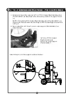
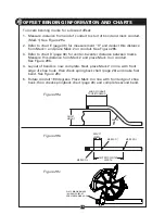
3. Next, mark conduit to desired length. Note that a minimum of 2" from the
end of the conduit to the front edge of the hook is required to eliminate
flattening the end of the conduit. See figure below.
NOTE: Stub-up and offset information can be found on pages 27-30 in this
manual or on the bending instruction decal on top of each bender.
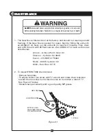
4. Rotate the bending shoe so that the bend degree pointer is at the minus
ten degree (-10
˚
) position as shown in the figure below.
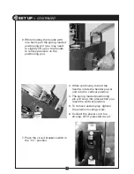
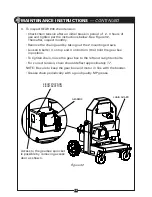
5. Place conduit into the bender. The conduit should slide over the roller
support, through the shoe groove and into the hook. The bending mark
should be at the front (outside) edge of the hook. See figure below.
6. After consulting the springback chart (found on page 28 in this manual or
on the bender instruction decal on the top of each bender), slide the bend
angle limit switch to the desired degree. NOTE: If you do not want to use
the bend angle limit switch, slide it clockwise as far as possible (about
105°). See pages 14 and 15 for bend angle limit switch information.
7. Place the pendant switch in the “BEND” position. Press the “JOG”
button and advance the bender shoe. Be sure to check the alignment of
the bending mark as the rotating shoe locks the conduit into position.
Advance the bender shoe to desired degree of bend. When the bend
degree pointer reaches the bend angle limit switch, the bender will stop.
8. To release the conduit, place the pendant switch in the “UNLOAD”
position. Press the “JOG” button and reverse the shoe far enough to
release the conduit. The conduit can now be removed.


