


29
OFFSET BENDING INFORMATION AND CHARTS
Figure 29a
Figure 29b
Figure 29c
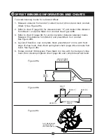
To locate bending marks for a desired offset:
1. Measure distance from end of conduit to start of bend and mark conduit.
(Mark 1) See Figure 29a
2. Refer to chart E (page 30) for measurement “X" and deduct this distance
from Mark 1 and place Mark 2 on conduit. See Figure 29b.
3. Refer to chart D (page 30) for center-to-center distance between marks.
Measure this distance from Mark 2 and place Mark 3 on conduit.
See Figure 29b.
4. Layout of bends is now complete. Next, place Mark 2 in line with front
edge of shoe hook, then check springback chart (page 28) and make first
bend. See Figure 29c.
5. Rotate conduit 180 degrees. Place Mark 3 in line with front edge of shoe
hook, then check springback chart (page 28) and complete second bend.
DEDUCT
LENGTH
MARK NO. 1
MARK NO. 3
CENTER TO CENTER
LENGTH
MARK NO. 2
END OF CONDUIT
TO START OF BEND
OFFSET
HEIGHT
ANGLE
PLACE BENDING MARK
IN LINE WITH FRONT
EDGE OF BENDING HOOK


