

Assembly & Set-Up
3
9
Contents of Crate
One Lawn Tractor
•
One Oil Drain Hose
•
One Deck Wash Hose Coupler
•
One Z-Force S Tractor Operator’s
•
Manual
One Engine Operator’s Manual
•
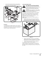
Tractor Preparation
Remove the upper crating material from the shipping pallet,
1.
and cut any bands or tie straps securing the tractor to the
pallet.
If the deck is not in the highest mowing position (pushed all
2.
the way forward), use the deck lift pedal to raise the deck to
its highest position. Refer to the Controls & Features section
for instructions on raising and lowering the deck.
Disengage the parking brake.
3.
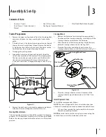
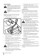
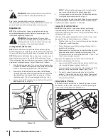
Engage the transmission bypass rods on each side of the
4.
tractor; then carefully roll the tractor off the shipping pallet.
The transmission bypass rods (one for each the RH and LH
transmission) are located on the rear of the tractor, just
inside each rear wheel. Disengage the bypass rods. See Fig.
3-1.
Remove the deck wash system nozzle adapter and oil drain
5.
tube from the manual bag and store for future use.
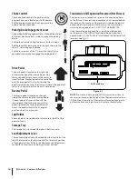
Steering Wheel Column
The steering wheel column is tilted all the way back for shipping
purposes. To tilt the column forward, press the steering tilt pedal.
Release the steering tilt pedal when the column is in the desired
position.
Steering Wheel
Remove the hardware for attaching the steering wheel
1.
from beneath the steering wheel cap. Carefully pry off the
steering wheel cover to remove the hardware.
With the wheels of the tractor pointing straight forward,
2.
place the steering wheel over the steering shaft.
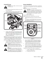
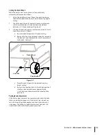
Place the flat washer and belleville washer over the
3.
steering wheel and secure with the hex screw. See Fig. 3-2.
Place the steering wheel cover over the center of the
4.
steering wheel and push downward until it “clicks” into
place.
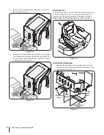
Install Operator’s Seat
To install the seat proceed as follows:
NOTE:
The seat is shipped with the seat switch and seat pan
attached. A second person may be needed to to hold the seat.
Cut any straps securing the seat assembly to the tractor.
1.
Remove any packing material.
NOTE:
Be careful not to cut the wiring harness connecting the
seat and the seat switch in the bottom of the seat.
Keyhole Slot
Transmission
Bypass Rods
Figure 3-1
Steering Wheel Cover
Hex Screw
Flat Washer
Steering Wheel
Steering Wheel
Column
Belleville Washer
Figure 3-2
Содержание Z-Force S 54
Страница 31: ...Attachments Accessories 10 31 Part No Part 19A70012100 54 Triple Bagger 19A70018100 Headlight Kit ...
Страница 32: ...Notes 11 32 ...
Страница 33: ...33 Section 11 Notes ...