


25
s
ectiOn
7 — s
ervice
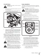
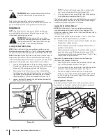
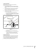
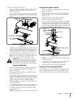
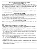
Using a
3.
1⁄2
” drive in the idler assembly turn the wrench
towards the back of the tractor and slide the belt off the
PTO pulley. See Fig. 7-4.
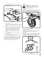
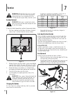
Pull the cotter pins out of the four deck lift adjustment
4.
brackets. See Fig. 7-5.
CAUTION:
The deck lift helper springs will cause
the deck lift pedal to slam to the highest position if
the click pin is not in front of the pedal.
Slide the links off the pins.
5.
NOTE:
It may be easier to place the deck lift pedal in
the transport postion when sliding the deck out from
underneath the tractor.
Jack up the rear-end of the tractor using the rear bumper.
6.
Slide the deck out from underneath the tractor to the right
7.
side.
Deck Installation
Install the deck on the tractor as follows:
Place the deck lift pedal in the highest mowing position
1.
and secure it by placing the click pin behind the pedal.
Refer to Fig. 7-3.
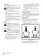
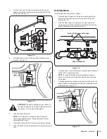
Slide the deck under the tractor on the right side of the
2.
tractor lining up the deck lift adjustment brackets and the
deck lift brackets on the deck. See Fig. 7-6.
Once the deck is under the tractor, move the deck lift pedal
3.
to the lowest mowing position.
NOTE:
To make the brackets line up properly it may be
necessary to place a small block of wood under each side
of the deck.
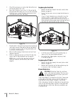
Once the brackets are properly aligned, slide the pin on the
4.
deck lift adjustment bracket into the lift bracket and secure
with cotter pins. See Fig. 7-7.
Idler Assembly
Figure 7-4
Cotter
Pin
Figure 7-5
Deck Lift Adjustment Brackets
Deck Lift Brackets
Figure 7-6
Figure 7-7
Cotter
Pin
Bracket Pin
Содержание Z-Force S 54
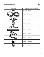
Страница 31: ...Attachments Accessories 10 31 Part No Part 19A70012100 54 Triple Bagger 19A70018100 Headlight Kit ...
Страница 32: ...Notes 11 32 ...
Страница 33: ...33 Section 11 Notes ...