background image

26

s

ectiOn

 7— s

ervice

Replacing the Deck Belt

Remove the deck from beneath the tractor, (refer to Deck 

1. 

Removal on page 24).
Remove the hex washer screws securing the belt covers to 

2. 

the deck.
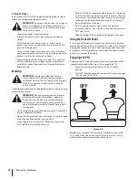
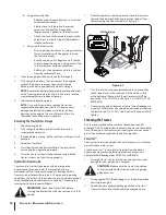
Using a 

3. 

1⁄2

” socket breaker bar or socket ratchet insert the 

male end into the 1⁄2

” square opening in the lower idler 

arm assembly and pull the idler arm clockwise. See Fig. 7-9. 

While holding the idler arm back, loosen the deck belt from 

the pulley and slide the belt away from the pulley.

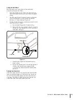
Install the new deck belt around the spindle pulleys as 

4. 

shown in Fig. 7-8 and reinstall the belt covers.
Reinstall the deck following the instructions in Deck 

5. 

Installation on page 25.

Replacing the PTO Belt

Remove the deck from beneath the tractor, (refer to Deck 

1. 

Removal on page 23).
Replace the PTO belt and reinstall the deck following the 

2. 

instructions in Deck Installation on page 25.

Mower Blade Care

WARNING! 

Protect your hands by using heavy 

gloves when handling the blades. When servicing 

the mower deck, be careful not to cut yourself on 

the sharpened blades.

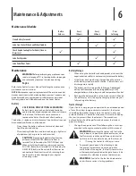
The cutting blades must be kept sharp at all times. Sharpen the 

cutting edges of the blades evenly so that the blades remain 

balanced and the same angle of sharpness is maintained. 
If the cutting edge of a blade has already been sharpened many 

times, or if any metal separation is present, it is recommended 

that new blades be installed. New blades are available at your 

authorized dealer.

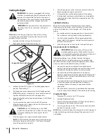
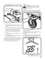
After all four cotter pins are secure, slide the deck forward 

5. 

and hook the deck to the U-rod.

Route the PTO belt as shown in Fig. 7-8. After routing the 

6. 

belt around the PTO pulley, use a 

1⁄2

” drive in the idler pulley 

bracket and turn towards the back of the tractor to finish 

routing the belt around the idler pulley.

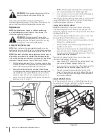
Place the deck in the highest mowing position by removing 

7. 

the click pin and push the pedal forward and rock back to 

lock into the transport position, locking behind the notch 

on the front of the index plate. 
Refer to the Maintenance & Adjustments section to level 

8. 

the deck if required.
Make sure the proper tension is on the belt. To adjust the 

9. 

tension, refer to “Adjusting Belt Tension” on page 22.

NOTE: 

Before using the tractor double-check the belt 

routing to make sure that the belt has been routed 

properly.

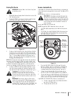
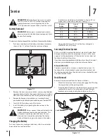
PTO Pulley

PTO Belt

Deck Belt

Figure 7-8

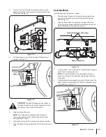
Idler Arm

Figure 7-9

Содержание Z-Force S 54

Страница 1: ...Practices Set Up Operation Maintenance Service Troubleshooting Warranty WARNING READ AND FOLLOW ALL SAFETY RULES AND INSTRUCTIONS IN THIS MANUAL BEFORE ATTEMPTING TO OPERATE THIS MACHINE FAILURE TO COMPLY WITH THESE INSTRUCTIONS MAY RESULT IN PERSONAL INJURY Z Force S 54 Form No 769 06499 October 20 2010 ...

Страница 2: ...ications for various models Characteristics and features discussed and or illustrated in this manual may not be applicable to all models We reserve the right to change product specifications designs and equipment without notice and without incurring obligation If you have any problems or questions concerning the machine phone your local Cub Cadet dealer or contact us directly Cub Cadet s Customer ...

Страница 3: ...jects which ricochet can cause serious injury to the eyes Wear sturdy rough soled work shoes and close fitting 9 slacks and shirts Loose fitting clothes and jewelry can be caught in movable parts Never operate this machine in bare feet or sandals Be aware of the mower and attachment discharge direction 10 and do not point it at anyone Do not operate the mower without the discharge cover or entire ...

Страница 4: ...hat operators age 60 years and above are 28 involved in a large percentage of riding mower related injuries These operators should evaluate their ability to operate the riding mower safely enough to protect themselves and others from serious injury If situations occur which are not covered in this manual use 29 care and good judgment Contact your customer service representative for assistance Slop...

Страница 5: ...d allow extra distance to stop 12 Do not shift to neutral and coast downhill 13 Service Safe Handling of Gasoline To avoid personal injury or property damage use extreme 1 care in handling gasoline Gasoline is extremely flammable and the vapors are explosive Serious personal injury can occur when gasoline is spilled on yourself or your clothes which can ignite Wash your skin and change clothes imm...

Страница 6: ...o improper performance and compromise safety Do not change the engine governor settings or over speed 12 the engine The governor controls the maximum safe operating speed of the engine Maintain or replace safety and instruction labels as 13 necessary Observe proper disposal laws and regulations for gas oil 14 etc to protect the environment According to the Consumer Products Safety Commission 15 CP...

Страница 7: ...semble and operate WARNING ROTATING BLADES Do not put hands or feet near rotating parts or under the cutting deck Contact with the blade s can amputate hands and feet WARNING THROWN OBJECTS This machine may pick up and throw and objects which can cause serious personal injury WARNING THROWN OBJECTS This machine may pick up and throw and objects which can cause serious personal injury BYSTANDERS Ke...

Страница 8: ...NG Do not operate your lawn mower on such slopes Do not mow on inclines with a slope in excess of 15 degrees a rise of approximately 2 1 2 feet every 10 feet A riding mower could overturn and cause serious injury Operate riding mowers up and down slopes never across the face of slopes Operate Z Force S zero turn tractors across the face of slopes rather than up and down Begin with the first pass a...

Страница 9: ...lumn is tilted all the way back for shipping purposes To tilt the column forward press the steering tilt pedal Release the steering tilt pedal when the column is in the desired position Steering Wheel Remove the hardware for attaching the steering wheel 1 from beneath the steering wheel cap Carefully pry off the steering wheel cover to remove the hardware With the wheels of the tractor pointing st...

Страница 10: ... To adjust the position of the seat push the seat adjustment lever to the left Slide the seat forward or rearward to the desired position then release the adjustment lever Make sure seat is locked into position before operating the tractor See Fig 3 5 Install the Rear Hitch Bracket Remove the hex flange screws and flange lock nuts that 1 secure the hitch bracket and muffler mount bracket to the bu...

Страница 11: ...ch the red cable to the positive battery terminal with the bolt and hex nut See Fig 3 8 Remove the plastic cover if present from the negative 2 battery terminal and attach the black cable to the negative battery terminal with the bolt and hex nut See Fig 3 8 Position the red rubber boot over the positive battery 3 terminal to help protect it from corrosion NOTE If the battery is put into service a...

Страница 12: ...cking behind the notch on the front of the index plate Remove and replace the lock rod into the desired height index hole then push pedal forward and rock forward to unlock and slowly allow the pedal to move back until it reaches the lock rod Ignition Switch Module Warning Never leave a running machine unattended Always disengage PTO set parking brake stop engine and remove key to prevent unintend...

Страница 13: ...ll flash as described for five minutes every time the tractor s engine is started during this maintenance interval Follow the oil change intervals provided in the engine manual HOURS 1 10 PTO BLADE P ARK BRAKE OIL BA TT Indicator Panel Features Battery Indicator Illuminates and the battery voltage is displayed briefly when the ignition switch it turned to the ON position Illuminates to indicate th...

Страница 14: ...e faster the tractor will travel The pedal will return to its original position when it s not pressed Cup Holder The cup holder is located on the LH console to the left of the operator s seat Storage Tray The storage tray is located at the rear of the LH console Seat Adjustment Lever The seat adjustment lever is located below the front left of the seat The lever allows for adjustment of the fore t...

Страница 15: ...l minutes to cool before refueling Tighten the fuel cap securely Before Operating Your Tractor Before you operate the tractor study this manual carefully to familiarize yourself with the operation of all the instruments and controls It has been prepared to help you operate and maintain your tractor efficiently This engine is certified to operate only on clean fresh unleaded regular gasoline For be...

Страница 16: ...ear or below freezing ensure the correct viscosity motor oil is used in the engine and the battery is fully charged Start the engine as follows Be sure the battery is in good condition A warm battery 1 has much more starting capacity than a cold battery Use fresh winter grade fuel Winter grade gasoline has 2 higher volatility to improve starting Do not use gasoline left over from summer Follow the...

Страница 17: ...king brake If leaving the tractor unattended also turn the engine off and remove the ignition key Reverse Caution Mode The REVERSE CAUTION MODE position of the key switch module allows the tractor to be operated in reverse with the blades PTO engaged NOTE Mowing in reverse is not recommended Warning Use extreme caution while operating the tractor in the REVERSE CAUTION MODE Always look down and be...

Страница 18: ...charged material to ricochet back toward the operator Do not mow at high ground speed especially if a mulch kit or grass collector is installed Do not cut the grass too short Short grass is prone to weed growth and yellows quickly in dry weather Always operate the tractor with the throttle lever in the FAST rabbit position while mowing For best results it is recommended that the first two laps be ...

Страница 19: ...cted to the correct terminals reversing them could result in serious damage to your engine s alternating system Battery Storage When storing the tractor for extended periods disconnect the 1 negativebatterycable Itisnotnecessarytoremovethebattery All batteries discharge during storage Keep the exterior 2 of the battery clean especially the top A dirty battery will discharge more rapidly The batter...

Страница 20: ...n tractor is equipped with dual integrated hydrostatic pumps transaxles that are sealed and are maintenance free However this model is equipped with a transmission oil expansion reservoir Under normal operating conditions the oil level in the expansion reservoir does not need to be checked and no additional oil is needed If checking the reservoir oil level proceed as follows WARNING Check the oil ...

Страница 21: ...ort on your decks 3 surface See Fig 6 2 Turn the water on 4 While sitting in the operator s position on the tractor start 5 the engine and place the throttle lever in the FAST rabbit position Move the tractor s PTO Blade Engage into the ON position 6 Remain in the operator s position with the cutting deck 7 engaged for a minimum of two minutes allowing the underside of the cutting deck to thorough...

Страница 22: ...k hanger link is not adjustable and is used to help adjust the other hanger links Using a wrench raise or lower the left side of the deck by 4 turning the adjustment gears See Fig 6 5 The deck is properly leveled when both blade tip measurements are equal Retighten the hex bolt on the front left deck hanger bracket when proper adjustment is achieved Leveling the Deck Front To Rear NOTE Check the t...

Страница 23: ...l to its highest setting a Remove the front and rear deck wheels by removing b the lock nuts and shoulder bolts which secure them to the deck See Fig 6 7 Place the deck lift pedal in the desired mowing c height setting Reinsert the shoulder bolts with each gauge wheel d into the index hole that leaves approximately inch between the bottom of the wheel and the pavement Parking Brake Adjustment If t...

Страница 24: ...echarge the battery after the tractor has been stored for a period of time A voltmeter or load tester should read 12 6 volts DC or higher across the battery terminals See Fig 7 2 Charge the battery with a 12 volt battery charger at a MAXIMUM rate of 10 amps Servicing Electrical System A fuse is installed to protect the tractor s electrical system from damage caused by excessive amperage Always use...

Страница 25: ...7 side Deck Installation Install the deck on the tractor as follows Place the deck lift pedal in the highest mowing position 1 and secure it by placing the click pin behind the pedal Refer to Fig 7 3 Slide the deck under the tractor on the right side of the 2 tractor lining up the deck lift adjustment brackets and the deck lift brackets on the deck See Fig 7 6 Once the deck is under the tractor mo...

Страница 26: ...ades must be kept sharp at all times Sharpen the cutting edges of the blades evenly so that the blades remain balanced and the same angle of sharpness is maintained If the cutting edge of a blade has already been sharpened many times or if any metal separation is present it is recommended that new blades be installed New blades are available at your authorized dealer After all four cotter pins are...

Страница 27: ...he blades Replace any blade with severe nicks or dents that cannot 3 be removed by filing Check the balance of the blade after sharpening by placing 4 it on a blade balancer Do not use un balanced blades If the blade dips on one end file stock off of the cutting 5 surface on that end NOTE Replace any blades that cannot be easily balanced Changing the Spindle Assembly Remove the deck from beneath t...

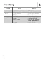
Страница 28: ...ssure 3 Perform side to side deck adjustment 1 Sharpen or replace blade 2 Check tire pressure in all four tires 3 Mower will not mulch grass If Equipped w Mulching Kit Engine speed too low 1 Wet grass 2 Excessively high grass 3 Dull blade 4 Place throttle in FAST rabbit position 1 Do not mulch when grass is wet 2 Mow once at a high cutting height then 3 mow again at desired height or make a narrow...

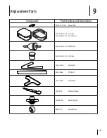
Страница 29: ...n KH 12 132 02 S Spark Plug KH 32 083 06 S Air Filter KH 32 083 08 S Pre Cleaner KH 25 050 22 S1 Fuel Filter KH 52 050 02 S Oil Filter 754 04137A Deck Belt 954 04262 PTO Belt 754 04250 Drive Belt 02005018 Mowing Blade 618 04426 Deck Spindle 634 3159 Deck Wheel ...

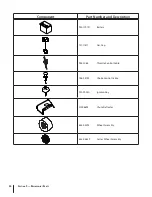
Страница 30: ...onent Part Number and Description 925 1707D Battery 751 11817 Gas Cap 946 1086 Throttle Control Cable 746 04752 Choke Control Cable 925 2054A Ignition Key 01006693 Chute Deflector 634 04295 Wheel Assembly 634 04629 Caster Wheel Assembly ...

Страница 31: ...Attachments Accessories 10 31 Part No Part 19A70012100 54 Triple Bagger 19A70018100 Headlight Kit ...

Страница 32: ...Notes 11 32 ...

Страница 33: ...33 Section 11 Notes ...

Страница 34: ...at cause the failure of a warranted part to be identical in all material respects to that part as described in MTD Consumer Group Inc s application for certification The warranty period begins on the date the outdoor equipment engine is delivered to an ultimate purchaser or first placed into service The warranty period is two years Subject to certain conditions and exclusions as stated below the w...

Страница 35: ...till eligible for warranty coverage Further the coverage under this warranty extends only to parts that were present on the off road engine and equipment purchased The following emission warranty parts are covered if applicable 1 Fuel Metering System Cold start enrichment system soft choke Carburetor and internal parts or fuel injection system Fuel pump Fuel tank 2 Air Induction System Air cleaner...

Страница 36: ...overage if the hour meter or any part thereof is altered modified disconnected or otherwise tampered with HOW TO OBTAIN SERVICE Warranty service is available WITH PROOF OF PURCHASE AND APPLICABLE MAINTENANCE RECORDS through your local authorized service dealer To locate the dealer in your area In the U S A Check your Yellow Pages or contact Cub Cadet LLC at P O Box 361131 Cleveland Ohio 44136 0019...

Отзывы: