- 10 -
w w w . C T C U . c o m
There are 16 VLAN groups available. For a group, enter the VID and then
select how the packet is sent out of that port (two fiber and two electrical).
The packet can be sent un-modified, sent untagged (meaning tag will be
removed), sent tagged or dropped as a non-member.
If a packet is double tagged, the untag process will only remove the outer
tag. The packet will still egress with the original inner tag.
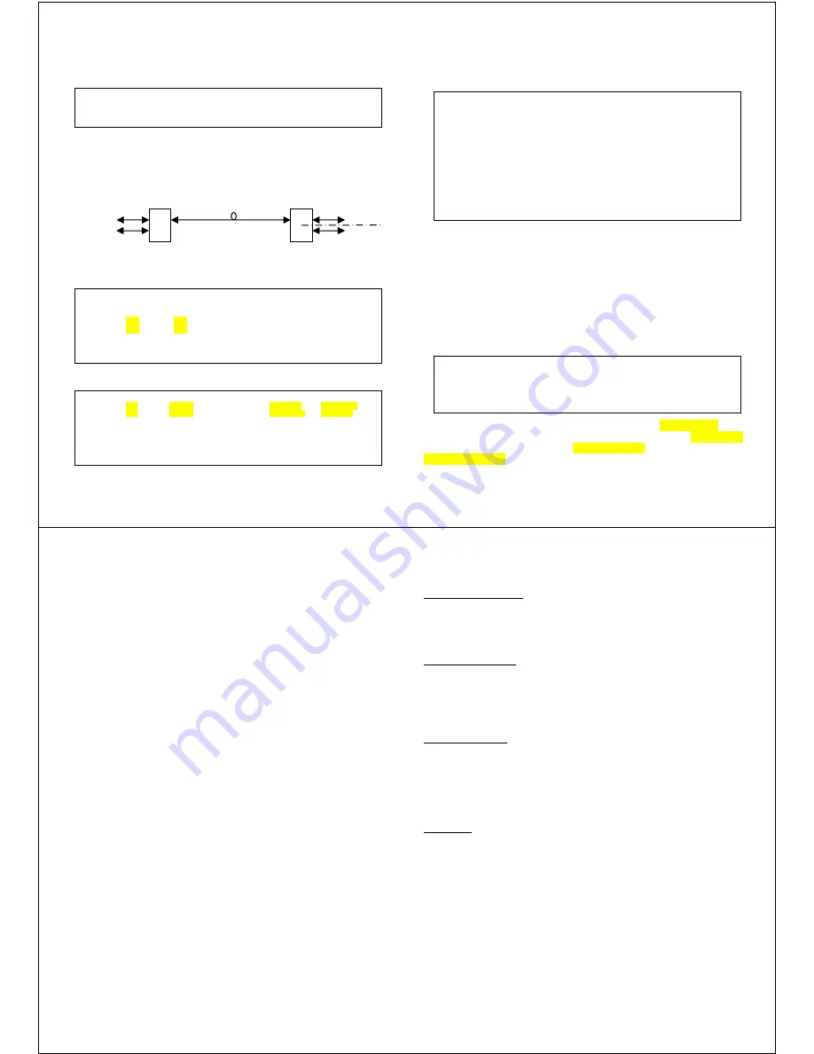
Application Example
Step 1. Configure the FRM220A-1002ES Ethernet LAN ports to add tag for
packets coming from LAN A and LAN B.
Step 2. Go to the static VLAN menu (menu item “Z”).
----------------------------------------------------------------------
Egress mode Select :
<1>: Unmodified <2>: Untagged <3>: Tagged <4>: Nonmember
<ESC> Go to previous menu. Please select an item.
Connection
carrying VID
100 & 200
Switch
Optical
RJ45
1002ES
SFP
SFP
RJ45
RJ45
RJ45
LAN-A
VID=100
LAN-B
VID=200
LAN-A
LAN-B
<< 802.1Q VLAN status and Configuration >>
Port 1: <1> :VID [1] <2> :QinQ Support [Disable]
Port 2: <3> :VID [1] <4> :QinQ Support [Disable]
Port 3: <5> :VID [100] <6> :QinQ Support [Disable]
Port 4: <7> :VID [200] <8> :QinQ Support [Disable]
<V> VLAN Tag Function [ Enable ]
<T> Tag Type (Hex) [8100]
<Z> Go to VLAN Table Configuration Page.
Item | VLAN ID | Port 1 | Port 2 | Port 3 | Port 4
< 0 > | 100 | Tagged | Unmodified | Untagged | Nonmember
< 1 > | 200 | Tagged | Unmodified | Nonmember | Untagged
< 2 > | 1 | Unmodified | Unmodified | Unmodified | Unmodified
Snip %<
< e > | 1 | Unmodified | Unmodified | Unmodified | Unmodified
< f > | 1 | Unmodified | Unmodified | Unmodified | Unmodified
<ESC>:Go to Port VID Configuration Page.
- 11 -
w w w . C T C U . c o m
Link Loss Forwarding
Link Loss Forwarding (LLF) is a method to report loss of Rx from any fiber
or UTP port and effectively stop Tx on any other fiber or UTP port. Since
FRM220A-1002ES has 4 ports, the LLF function is configured via a 4x4
matrix table and with 'and' or 'or' logic operations.
Example 1: FX port 1 Tx off if any port 2,3,4 Rx loss:
keyin 1,2,3 and keyin 0 to change 'and' to 'or'
Example 2: FX port 1 Tx off if all ports 2,3,4 Rx loss
keyin 1,2,3 and leave Port 1 as 'And'
Example 3: FX port 1 Tx off if port 3 Rx loss
keyin 2 (only one selected so logic doesn't care)
Press ‘s’ key to confirm and save settings.
Device
From the Main menu, press “5” to enter the Device menu
The entire device can be taken offline by disabling it. “Flow control”
(802.3X) is enabled by default, but may be disabled here. The “Port Reset”
function will warm start the switch. “Factory Default” will return all settings.
“Store parameters” is required so settings are remembered at next power
up.
<< Link Loss Forwarding Configuration >>
| Condition |
| Port 1 | Port 2 | Port 3 | Port 4 |
| Logical | Link Loss| Link Loss| Link Loss| Link Loss|
-----------------+----------+----------+----------+----------+----------|
Port 1 Power Off | <0>[AND] | | <1>[ ] | <2>[ ] | <3>[ ] |
-----------------+----------+----------+----------+----------+----------|
Port 2 Power Off | <4>[AND] | <5>[ ] | | <6>[ ] | <7>[ ] |
-----------------+----------+----------+----------+----------+----------|
Port 3 Power Off | <8>[AND] | <9>[ ] | <A>[ ] | | <B>[ ] |
-----------------+----------+----------+----------+----------+----------|
Port 4 Power Off | <C>[AND] | <D>[ ] | <E>[ ] | <F>[ ] | |
-----------------+----------+----------+----------+----------+----------+
<R> :Reset Settings.
<S> :Confirm and Save Settings.
<ESC>:Go to Previous Menu.
<< Device Status and Configuration >>
<1> Device Active [ Enable ]
<2> Flow Control [ Enable ]
<3> Port Reset
<4> Factory Default
<5> Store Parameters
- 12 -
w w w . C T C U . c o m
Upgrading
The FRM220A-1002ES card may be firmware upgraded when it is placed
in the FRM220 with NMC management card. The user may use a local
console connection to the NMC, a remote Telnet (IP) connection, or a Web
based (HTTP) connection with any available browser. The NMC
communicates to all cards through a serial control bus. The upgrade code is
transferred to the NMC by way of TFTP server. All of these mentioned
upgrade methods are well documented in the FRM220-NMC Operation
Manual.
About SFP Units
The FRM220A-1002ES accepts any SFP unit that complies with the MSA
standard and is rated for a data rate of 1.25Gbps for GbE or 125/155Mbps
for FE. Follow all ESD precautions when handling the card and SFP
modules. Fiber optic components and cables are very sensitive to dirt, dust
and mishandling, especially in high-speed networks. Dirty or mistreated
fiber may cause errors and an unwanted degradation of signal quality.
Remove the dust caps on SFP and patch cables only when ready to plug in
optical cables.
Installation
CTC Union supplied SFP modules are of the Bale Clasp type. The bale
clasp SFP module has a bale clasp that secures the module into the SFP
cage.
•
Inserting a Bale Clasp SFP Module into a SFP cage
Step 1 Close the bale clasp upward before inserting the SFP module.
Step 2 Line up the SFP module with the port, and slide it into the cage.
•
Removing a Bale Clasp SFP Module
Step 1 Open the bale clasp on the SFP module. Press the clasp
downward with your index finger.
Step 2 Grasp the SFP module between your thumb and index finger and
carefully remove it from the SFP cage.
- 13 -
w w w . C T C U . c o m
Troubleshooting
UTP Port link problems
The TP port of the 1002ES supports 10/100/1000Base-T. Avoid Duplex
Mismatch conditions by connecting auto to auto or forced to forced.
The UTP port supports auto-polarity and auto MDI-X, so any straight Cat
5e or better cable will work.
FX Port link problems
The FX port supports FE or GbE by manual configuration only. The SFP
used must support FE or gigabit Ethernet speed depending on the setting.
There is no recognized standard for automatically determining FE or GbE
speed from the transceiver. For link problems please double check the
speed is set according to the SFP being deployed.
Other link problems
Check if LFP is enabled. If LFP is enabled, the converter requires good
link on both FX and TP ports. If either has no link, then the other will also
not link. So, if link testing, please disable LFP.
FX link can be check by using an LC simplex cable to loop the SFP Tx to
Rx. CAUTION: Do not do this when the TP port is linked to a live network or
a broadcast storm could result.
Conclusion
Once configuration has been confirmed and FX / TP ports check for link
state, most problems end up being cables. Swap different UTP and fiber
cables, and SFP modules before blaming the media converter.