


Chapter 2. Installation
2.8 Removal/Replacement Procedures
2.8.1 Order Wire Feature Module Removal / Replacement
***CAUTION***
This procedure should only be performed by qualified service personnel. In addition, all
power connections must be removed before attempting to open the case.
The Order Wire feature is installed as separate daughter cards inside the pair of
FMUX04
.
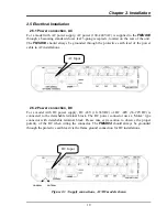
The front panel RJ-11 telephone connector routes to the OW (Order Wire) interface PCB. The
OW option provides a standard FXS connection that links to the remote
FMUX04
unit via the
fiber optical interface. Calls are placed simply by lifting the telephone off-hook. The remote
telephone will ring.
To install or remove the OW option;
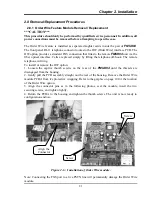
1. Loosen the captive thumb screws on the rear of the
FMUX04
until the threads are
disengaged from the housing.
2. Gently pull the PCB assembly straight out the rear of the housing. Remove the Order Wire
module PCBA from it's protective wrapping. Refer to the graphic on page 10 for the location
of the Order Wire option.
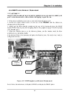
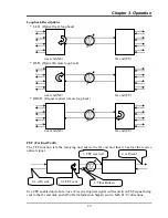
3. Align the connector pins as in the following photos, seat the module, insert the two
securing screws, and tighten lightly.
4. Return the PCBA to the housing and tighten the thumb screws. The unit is now ready to
configuration and use.
Screw
Sc
rew
Align the
Connector
Figure 2-6 : Installation of Order Wire module.
Note: Connecting the FXS port to a live PSTN line will permanently damage the Order Wire
module.
21
Содержание FMUX04
Страница 2: ......
Страница 16: ...Chapter 1 Introduction 16 This page left blank intentionally ...
Страница 61: ......