26
| English
2 610 A15 112 • 12.8.09
Working without Automatic Levelling (“OFF”)
When the automatic levelling is switched off, the lev-
elling of the axes is no longer monitored; the shock-
warning function is also switched off.
f
Position changes of the measuring tool are
not detected when the automatic levelling is
switched off.
As soon as a grade is set for an axis in horizontal posi-
tion, the automatic levelling is automatically switched
off regardless of the selected setting.
When the automatic levelling is switched off, the
measuring tool can be set up in any inclined position.
With the gradient plate (accessory), the measuring
tool can also be exactly inclined alongside an axis at
an angle larger than 10 % when in the horizontal posi-
tion.
Grade Setting in the Horizontal
Position
When the measuring tool is in the horizontal position,
grades to
±
10 % can be exactly set for both axes inde-
pendent from each other.
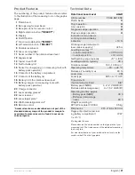
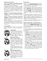
After switching on in the hori-
zontal position, the menu for
grade adjustment appears on
the display. To call up the
grade menu again, e.g. after changing the operating
mode, press the function-mode button
7
until
“SELECT/GRADE”
is indicated on the display. Then
press the left selection button
8
.
By briefly pressing the function-mode button
7
, you
can select the axis for which the grade is to be set.
The selected axis is marked with
“>”
. Set the desired
grade value with selection button
8
above
“+”
or
selection button
4
above
“–”
. To exit the grade menu,
press function-mode button
7
for 5 seconds.
The grade setting is stored when switching off the
measuring tool. To horizontally align the rotational
plane, set both grade values to 0.00 %.
The maximal grade of 10 % can only be reached when
the measuring tool is exactly horizontal. When
inclined, the maximal grade angle is reduced by the
inclined angle. When the set grade angle cannot be
reached,
“ERROR/GD TOO STEEP”
is indicated on
the display.
In this case, switch the measuring tool off, re-align it
and switch the measuring tool on again. If the measur-
ing tool is not re-positioned, it is automatically
switched off after 2 minutes.
To achieve the greatest possible accuracy for grading
work, the following points must be observed:
– Set up the measuring tool as level as possible
before switching on or setting a grade.
– The automatic levelling is switched off automati-
cally when the axes are inclined.
– When only one axis is inclined, the shock-warning
function for the second axis can be switched on.
The shock-warning function is deactivated for
approx. 30 seconds each time after changing the
grade value. When the shock-warning function is
actuated from position changes, the rotational plane
is exactly inclined again according to the stored
value after the levelling.
– When both axes are inclined, the shock-warning
function is automatically deactivated. Position
changes of the measuring tool are not detected.
– After position changes of the measuring tool when
both axes are inclined or when the shock-warning
function is shut off, switch the measuring tool off
and then on again. After switching on, the rota-
tional plane firstly levels out horizontal before
being exactly inclined with the stored values.
Grades in only one axis should be set at the Y-axis, as
the measuring tool can be easier aligned with the
alignment aids
12
alongside this axis.
Accuracy Check of the Measuring Tool
Influences on Accuracy
The ambient temperature has the greatest influence.
Especially temperature differences occurring from the
ground upward can divert the laser beam.
The deviations play a role in excess of approx. 20 m
measuring distance and can easily reach two to four
times the deviation at 100 m.
Because the largest difference in temperature layers
is close to the ground, the measuring tool should
always be mounted on a tripod when measuring dis-
tances exceeding 20 m. If possible, also set up the
measuring tool in the centre of the work area.
Apart from exterior influences, device-specific influ-
ences (such as heavy impact or falling down) can lead
to deviations. Therefore, check the accuracy of the
measuring tool each time before starting your work.
To check the accuracy, select rotational operation
and, if required, use the laser receiver to mark the cen-
tre of the rotating laser beam.
Should the measuring tool exceed the maximum devi-
ation during one of the tests, please have it repaired
by a Bosch after-sales service.
OBJ_BUCH-971-001.book Page 26 Wednesday, August 12, 2009 8:46 AM
Содержание AL-Series
Страница 2: ...2 2 610 A15 112 12 8 09 6 5 3 4 3 8 7 2 2 1 9 12 13 16 17 18 14 15 11 10 13 ALGR...
Страница 3: ...3 2 610 A15 112 12 8 09 19 21 22 23 24 20 25 B A...
Страница 4: ...4 2 610 A15 112 12 8 09 28 27 26 29 30 31 32 33 34 35 37 36 38 39 40 RC400X...
Страница 155: ...E 155 2 610 A15 112 12 8 09 f f 10 f f 2 IEC 60825 1 f f UV f f f f f f f CST berger 23 f 23...
Страница 158: ...158 E 2 610 A15 112 12 8 09 f f f 163 24 f f ON OFF 6 9 1 5 162 0 00 30 s 5 161 60 s ON OFF 6...
Страница 159: ...E 159 2 610 A15 112 12 8 09 7 ON OFF 6 LANG CAL QUIT 8 LANG 7 SELECT 6 X Y X Y 12 7 MODE 5 s 7 4 SELECT 8 SELECT...
Страница 163: ...E 163 2 610 A15 112 12 8 09 30 s 12 20 m 100 m 20 m 20 m Service Bosch 30 m 30 m 0 00 I 30 m...
Страница 165: ...E 165 2 610 A15 112 12 8 09 5 8 13 13 5 8 B 24 5 8 13 24 24 15 cm 23 23 23 1 9...
Страница 240: ...240 2 610 A15 112 12 8 09 f f 10 f f 2 IEC 60825 1 f f f f f f f f f CST berger 23 f 23...
Страница 243: ...243 2 610 A15 112 12 8 09 f f f 248 24 f f 6 9 1 5 247 0 00 30 5 245 60 6...
Страница 247: ...247 2 610 A15 112 12 8 09 OFF f 10 10 7 SELECT GRADE 8 7 8 4 7 5 0 00 10 ERROR GD TOO STEEP 2 30 Y 12...
Страница 249: ...249 2 610 A15 112 12 8 09 10 10 x 0 1 1 d 1 f f f 22 600 1 25 3 25 252 5 8 13 13 5 8 24 5 8 13 24 24 15 23 23...
Страница 250: ...250 2 610 A15 112 12 8 09 23 1 9 14 ERROR BATTERY LOW ERROR X TOO STEEP X ERROR Y TOO STEEP Y Bosch...
Страница 255: ...255 2 610 A15 112 12 8 09 Bosch 10 oe e e e oe e e e 251 252...
Страница 256: ...256 2 610 A15 112 12 8 09 f f 10 f f 2 IEC 60825 1 f f f f f f f f f CST berger 23 f 23...
Страница 259: ...259 2 610 A15 112 12 8 09 f f f 263 24 f f 6 9 1 5 263 0 00 30 5 261 60 6 7 6 LANG CAL QUIT 8 LANG 7 SELECT...
Страница 263: ...263 2 610 A15 112 12 8 09 10 7 SELECT GRADE 8 7 8 4 7 5 0 00 10 ERROR GD TOO STEEP 2 30 Y 12 20 100 20 20 Bosch...
Страница 265: ...265 2 610 A15 112 12 8 09 A 22 600 1 25 3 25 267 5 8 13 13 5 8 B 24 5 8 13 24 24 15 23 23 23 1 9...
Страница 270: ...270 2 610 A15 112 12 8 09 Bosch 10 C a a c ep i i i C a a c ep i i i 267 267...
Страница 285: ...285 2 610 A15 112 12 8 09 f f 10 f f 2 IEC 60825 1 f f f f f f f f f CST berger 23 f 23...
Страница 288: ...288 2 610 A15 112 12 8 09 f f f 292 24 f f 6 9 1 5 292 0 00 30 5 290 60 s 6 7 6 LANG CAL QUIT 8 LANG 2 7 SELECT 6...
Страница 292: ...292 2 610 A15 112 12 8 09 10 7 SELECT GRADE 8 7 8 4 5 s 7 0 00 10 ERROR GD TOO STEEP 2 30 s Y 12 20 m 100 m 20 m 20 m...
Страница 294: ...294 2 610 A15 112 12 8 09 22 600 min 1 25 3 25 297 5 8 13 13 24 5 8 13 24 24 15 cm 23 23 23...

