4
9. WATER DRAINING
Condensation waters, which come from the evaporator and from the evaporative shelves of the refrigeration cabin
during defrosting, drain as follows:
•
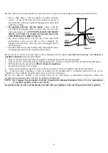
Set the operation switch on position 0 (figure 5-A)
•
Unscrew the screw that is located at the top of the metallic grill panel (that covers the engine-room) and
holds it on the metallic support of the thermometer (top-left of the appliance). Next, remove the fitted
grill panel, moving it slightly upwards so that it disengages from the screws and then pull it towards
yourself.
•
Pull the drainage towards you (see the figure 5-B).
•
Place a container beneath the drainage pipe for collecting the water (see the figure 5-B).
•
Remove the outer plug pulling it gently (see the figure 5-B)
•
Remove the grill panel which is located at the bottom of the freezer (from inside the cabin).
•
Remove the inner drainage plug that is located on the freezer’s bottom inside the cabin.
•
Once the waters are drained, repeat the steps in the inverse order and start operating the appliance by
setting the operation switch on position I.
10. CLEANING OF THE FREEZER
For the purpose of cleaning the freezer interior,
DO NOT
use sharp objects or chemicals in order to accelerate the
process of defrosting. Follow the instruction that is recommended by the manufacturer, i.e. the use of lather in lukewarm
water.
11. CLEANING OF THE CONDENSER (figure 6)
For proper operation of the appliance, the condenser must be free of dust. Clean the condenser at least once in
three months, as follows:
Unplug the appliance.
Remove the metallic grill panel from the appliance following the instructions in paragraph 9.
Clean the condenser by using a soft brush or a vacuum cleaner.
Replace the grill panel back on the holding screws.
Insert the plug and switch on the appliance.
LIGHT
SWITCH
THERMOMETER
OPERATION
SWITCH
THERMOSTAT
INNER
DRAINAGE PLUG
OUTER DRAINAGE
PLUG
DRAINAGE
PIPE
OUTER
DRAINAGE PLUG
WASTE WATER
COLLECTION CONTAINER
Figure 6
Figure 5-B
Figure 5-A


