background image

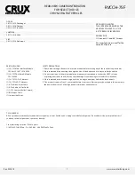
USING THE MENU BUTTONS

The installer has MENU options available. These buttons are o ered on the bottom side the main interface module.

Step 1

 -Use the 3 buttons on the bottom to adjust the following:

Button 1 = Menu
Button 2 = Up (+)
Button 3 = Down (-)

(From left to right)

INTERFACING SOLUTIONS

RVCCH-75F

REAR-VIEW CAMERA INTEGRATION 

FOR SELECT DODGE,

CHRYSLER & FIAT VEHICLES

www.cruxinterfacing.com

Rev. 042616

7

CONTRAST
BRIGHTNESS
SATURATION
POSITION H
POSITION V
IR AV1
IR AV2
GUIDE L
GUIDE R
GUIDE CNTRL
H-SIZE
V-SIZE

MENU

(+) (-)

BOTTOM OF THE INTERFACE

OFF

NOTE: 

OFF is UP on the DIP Switch

Содержание RVCCH-75F

Страница 1: ...starting any of the installation procedures 2 We recommend disconnecting the negative side of the battery until ready to code the vehicle 3 Do not install any of the main modules near any major components or near the HVAC system as placing items near the HVAC may cause damage or overheating to the vehicle or interface 4 We recommend not disconnecting any of the air bag connections behind the dash ...

Страница 2: ...ESS CAN MODULE PLEASE TAP 6 PIN CONNECTOR FOR CAMERA POWER GROUND WIRE VIEW 1 2 3 4 5 6 6 PIN WIRE CODES 1 Yellow Contstant 12V 2 Red Acc 12V 3 Gray Ctrl Data 4 Black Ground 5 Green Reverse Trigger 6 White Switch Data CAMERA IN VIDEO 1 2 INPUTS ON DATALINK STATUS POWER STATUS DATALINK STATUS POWER STATUS 6 PIN male plug 8 PIN male plug BULLET CAMERA DIP SET RGB DATA PWR SWITCH AUDIO IN OUT LVDS OU...

Страница 3: ...ll the interface module Step 1 Remove the factory radio to gain access to the factory 22 Pin connector Located behind the radio Remove the factory 22 Pin connector Step 2 Using the provided 22 Pin T Harness mate both sides of the T Harness To the factory harness side and to the factory radio side Also connect the Green LVDS T Harness to the back of the display Top Unit and to the factory connector...

Страница 4: ...ion feature does not require activation This feature is permanently ON and will not disturb the navigation GPS performance DIP SWITCH DESCRIPTION IF NOT USING THE INPUT PLACE TO OFF DIP 1 External RGB Enable DIP 2 AV1 Enable DIP 3 AV2 Enable DIP 4 RGB IN On 480 OFF 1080p DIP 5 Rear View Camera Input Enable DIP 6 IR Programming DIP 7 Not Used Set to OFF DIP 8 OFF 8 4 ON 4 3 Screen 4 5 6 7 8 OFF 1 2...

Страница 5: ...ts connect the interface as described below Step 5 With the T Harness and LVDS harnesses properly connected use the 6 Pin harness to connect the smaller interface to the main interface box Step 6 Connect the large White 6 Pin and the smaller 8 Pin connectors to the main module Completing the connections of the two modules Be sure to CUT the GREEN wire and CONNECT the 6 PIN side of the GREEN wire t...

Страница 6: ...face to recognize the audio and video inputs please do the following Step 1 Connect the 6 Pin Video Adaptor to the main interface module This allows you 3 video inputs INPUT DESCRIPTIONS YELLOW VIDEO 1 INPUT WHITE VIDEO 2 INPUT RED REVERSE CAMERA INPUT GRAY WIRE OPTIONAL IR OUTPUT Step 2 Connect the 6 Pin Audio Adaptor to the main interface module This allows you 2 Audio inputs and 1 Audio output ...

Страница 7: ...the following Button 1 Menu Button 2 Up Button 3 Down From left to right INTERFACING SOLUTIONS RVCCH 75F REAR VIEW CAMERA INTEGRATION FOR SELECT DODGE CHRYSLER FIAT VEHICLES www cruxinterfacing com Rev 042616 7 CONTRAST BRIGHTNESS SATURATION POSITION H POSITION V IR AV1 IR AV2 GUIDE L GUIDE R GUIDE CNTRL H SIZE V SIZE MENU BOTTOM OF THE INTERFACE OFF NOTE OFF is UP on the DIP Switch ...

Страница 8: ...042616 8 SWITCHING AV INPUTS For the audio to be present from the AV sources make sure the AUX source is selected on the radio The interface also provides you with a optional Switch Button for toggling through the AV inputs RADIO TYPE 4 3 Press the MORE button on the control center to toggle the inputs Compatible radio 4 3 Screen ...

Страница 9: ...ICLES www cruxinterfacing com Rev 042616 9 COMPATIBLE RADIO 8 4 Screen Radio 2 Piece Radio SPECIFICATIONS Operation voltage 10 5 14 8V DC Stand by power drain 10mA Power consumption 4 8W Temperature range 40 C to 85 C Weight 190g Measurements box only B x H x T 15 2 x 9 x 2 1 cm SEPARATE CD SLOT ...

Страница 10: ...ay in the car Step 6 Route your power and RCA cable towards the front of the vehicle Step 1 After you have removed the 3rd brake light from the trunk lid use the supplied drilling template to begin drilling the hole on the back side of the brake light Step 2 Continue drilling through the back and into the front side of that brake light This will allow you a guide hole when you begin drilling on th...

Отзывы: