


4 5 6 7 8
OFF
1 2 3
MULTI
MEDIA
INTERFACE
CAN
MODULE
ON
DATALINK STATUS
POWER STATUS
D
POWER STATUS
6-PIN
(male plug)
8-PIN
(male plug)
*
6-PIN
(male plug)
VIDEO
INPUTS
DIP SET
RGB
DATA
PWR
4-PIN
(male plug)
RED/
POWER 12V
BLACK/
GROUND
VIDEO
(male plug)
*
PLEASE TAP 6-PIN CONNECTOR
FOR CAMERA POWER & GROUND
WIRE VIEW
1 2 3
4 5 6
6-PIN WIRE CODES
1. Yellow = Contstant 12V
2. Red = Acc 12V
3. Gray = Ctrl Data
4. Black = Ground
5. Green = Reverse Trigger
6. White = Switch Data
CAMERA IN
VIDEO 1 & 2
INPUTS
BULLET
CAMERA
RED/
REVERSE TRIGGER INPUT
YELLOW/
CONSTANT INPUT
BLACK/
GROUND INPUT
POWER DOWN
CIRCUIT
CUTH HERE
(GREEN/ PIN 5)
TAP THE RESERSE
LAMP SIGNAL
GREEN/
REVERSE OUTPUT
....
INTERFACING SOLUTIONS
RVCCH-75F
REAR-VIEW CAMERA INTEGRATION
FOR SELECT DODGE,
CHRYSLER & FIAT VEHICLES
www.cruxinterfacing.com
Rev. 042616
4
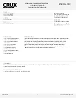
CONNECTING THE INTERFACE
Follow these steps to properly install the interface module.
Step 3
- Connect the 8-Pin connector on the T-Harness to the CAN interface module.
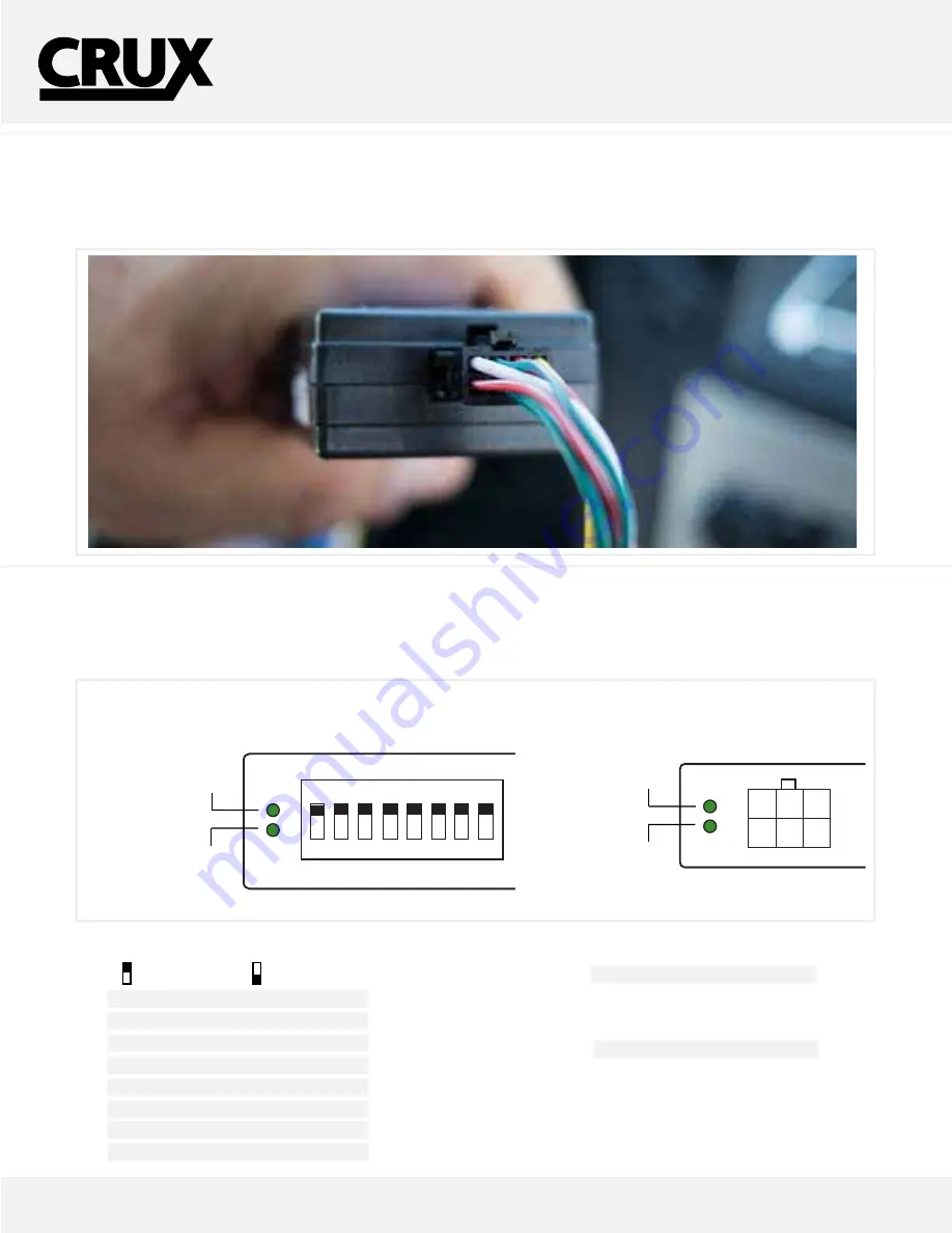
Step 4
- After connecting the module, set the proper dip switches to the “ON” position. Make sure to set the AV sources being used to the
“ON” position.
NOTE: The Video In-Motion feature does not require activation. This feature is permanently ON and will not
disturb the navigation GPS performance.
DIP SWITCH DESCRIPTION
IF NOT USING THE INPUT, PLACE TO OFF
DIP 1 =
External RGB Enable
DIP 2 =
AV1 Enable
DIP 3 =
AV2 Enable
DIP 4 =
RGB IN (On= 480/OFF= 1080p)
DIP 5 =
Rear-View Camera Input Enable
DIP 6 =
IR Programming
DIP 7 =
Not Used/ Set to OFF
DIP 8 = OFF
= 8.4”/
ON
= 4.3” Screen
4 5 6 7 8
OFF
1 2 3
MULTI
MEDIA
INTERFACE
CAN
MODULE
ON
DATALINK STATUS
POWER STATUS
DATALINK STATUS
POWER STATUS
6-PIN
(male plug)
8-PIN
(male plug)
*
6-PIN
(male plug)
VIDEO
INPUTS
DIP SET
RGB
DATA
PWR
4-PIN
(male plug)
RED/
POWER 12V
BLACK/
GROUND
VIDEO
(male plug)
*
PLEASE TAP 6-PIN CONNECTOR
FOR CAMERA POWER & GROUND
WIRE VIEW
1 2 3
4 5 6
6-PIN WIRE CODES
1. Yellow = Contstant 12V
2. Red = Acc 12V
3. Gray = Ctrl Data
4. Black = Ground
5. Green = Reverse Trigger
6. White = Switch Data
CAMERA IN
VIDEO 1 & 2
INPUTS
BULLET
CAMERA
RED/
REVERSE TRIGGER INPUT
YELLOW/
CONSTANT INPUT
BLACK/
GROUND INPUT
POWER DOWN
CIRCUIT
CUTH HERE
(GREEN/ PIN 5)
TAP THE RESERSE
LAMP SIGNAL
GREEN/
REVERSE OUTPUT
....
After each change of the DIP switch settings,
we recommend powering down the module,
then restarting the vehicle.
LED INDICATORS
DATALINK LED:
Blinking = BUS Detected.
OFF = Power Down/ Sleep mode.
POWER LED:
ON = Power On
OFF = Power OFF
MULTIMEDIA MODULE
CAN MODULE
UP=OFF
DOWN=ON
DATALINK STATUS


