background image

Trunk Subwoofer

019 0021

NOTES:

Please read first

• 

 Instructions show factory size speakers or speakers 
with adaptor brackets only.  Cutting or fabrication (not 
shown) will be required for other speaker sizes.

1.

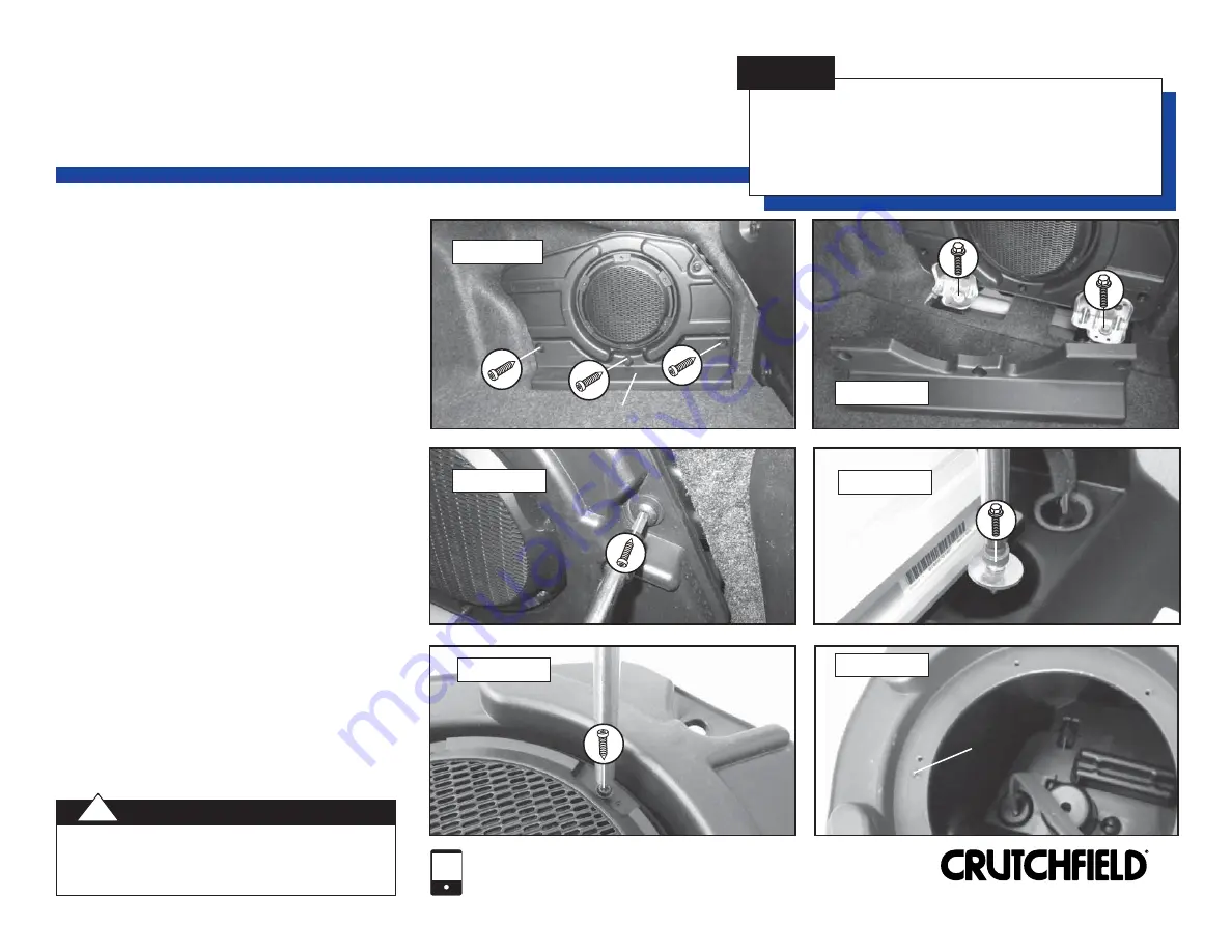
  Remove three (3) Torx T20 screws securing  


enclosure cover panel

.  Remove panel  


 (Figure 

1).

2.

  Remove one (1) Torx T40 screw and two (2)  


1/2” bolts securing enclosure to body.  


Disconnect wiring harness and remove  


enclosure (Figures 2 & 3).

3.

  Remove one (1) 8mm screw inside cavity    


on rear of enclosure and six (6) Torx T20    


screws on front of enclosure (Figures 4 & 5).

4.

  Remove grille, then pry up subwoofer.   


Disconnect wiring harnesses and remove.   


5.

 Break 

off 

alignment pins

 on mounting 


surface to allow proper fit of new speaker   

 (Figure 

6).

6.

  Place new speaker in location and mark new  


mounting holes.  Remove speaker and drill  


holes with a 1/8” bit.

7.

  Connect speaker wiring and secure speaker  

 to 

enclosure.

8.

  Test speaker operation and reassemble by  


reversing disassembly steps.

12

FIGURE 3

FIGURE 1

FIGURE 2

FIGURE 5

FIGURE 4

Enclosure Cover Panel

Enclosure Cover Panel

Alignment Pin

Alignment Pin
(1 of 2 shown)

(1 of 2 shown)

FIGURE 6

(1 of 6 screws shown)

(1 of 6 screws shown)

Copyright 2018  Crutchfield Corporation

1-800-955-9094

TECHNICAL SUPPORT

Always be careful when drilling or cutting in a vehicle.  WEAR 
EYE PROTECTION.  Be aware of things such as wiring, 
windows, fuel lines and safety devices.  Check depth and 
location to avoid damage to vehicle appearance.

CAUTION:

!

Содержание 019 0021

Страница 1: ...formation does so at his or its own risk If you find our instructions are different from your vehicle or if you have questions do not continue with your installation Contact our toll free technical support for assistance Before starting compare items on your invoice with items received Carefully check through packaging material If any item is missing please call Crutchfield Technical Support at 1 ...

Страница 2: ... 2 7mm screws exposed by removal of center vent panel Figure 4 6 Pry off lower receiver climate trimpanel and remove two 2 exposed 7mm screws Figure 5 7 Remove rubber mat in forward console tray Figure 6 Continued on the next page 019 0021 Factory Radio Removal Copyright 2018 Crutchfield Corporation FIGURE 6 1 800 955 9094 TECHNICAL SUPPORT FIGURE 1 FIGURE 2 FIGURE 3 FIGURE 4 FIGURE 5 Glove Box Ri...

Страница 3: ...mate control panel Figure 10 12 Remove console pocket tray Figure 11 13 Pry out receiver climate control panel to release four 4 clips Disconnect wiring harnesses and remove control panel Figure 12 Continued on the next page 019 0021 Factory Radio Removal continued Copyright 2018 Crutchfield Corporation 1 800 955 9094 TECHNICAL SUPPORT 3 FIGURE 7 FIGURE 8 FIGURE 9 FIGURE 10 FIGURE 11 FIGURE 12 Con...

Страница 4: ... screws securing display to dash Disconnect harness and remove display Figure 14 16 Remove three 3 7mm screws securing module to sub dash Lift module disconnect harnesses on radio chassis and remove chassis Figure 15 019 0021 Factory Radio Removal continued 4 FIGURE 13 FIGURE 15 Copyright 2018 Crutchfield Corporation 1 800 955 9094 TECHNICAL SUPPORT Factory Radio Chassis Factory Radio Chassis Disp...

Страница 5: ...rom Crutchfield 2 Hold receiver assembly near dash Connect receiver wiring adaptor to vehicle harness Using the antenna adaptor plug antenna lead into rear of receiver Plug in any other accessories to be used with the receiver 3 Slide assembly into dash and secure with screws previously removed 4 If installing a center dash speaker proceed to instructions on page 7 before reassembling dash 5 Test ...

Страница 6: ...area by reversing disassembly steps NOTES Please read first Instructions show factory size speakers or speakers with adaptor brackets only Cutting or fabrication not shown will be required for other speaker sizes Copyright 2018 Crutchfield Corporation 1 800 955 9094 TECHNICAL SUPPORT No speaker wiring adaptor is available at this time from Crutchfield for this speaker location It will be necessary...

Страница 7: ... thirteen 13 clips and remove vent panel Figure 2 3 Starting at the rear edge pry up center dash grille to release four 4 clips Remove grille Figure 3 4 Remove two 2 7mm screws securing speaker Pull out speaker disconnect and remove Figure 4 5 Make wiring connections following instructions on page 13 Return to this page to complete installation 6 Secure speaker to location with screws previously r...

Страница 8: ...screws along bottom edge of door panel Figure 4 Continued on the next page Copyright 2018 Crutchfield Corporation 1 800 955 9094 TECHNICAL SUPPORT NOTES Please read first Instructions show factory size speakers or speakers with adaptor brackets only Cutting or fabrication not shown will be required for other speaker sizes FIGURE 1 FIGURE 2 FIGURE 3 FIGURE 4 Screw Cover Screw Cover Power Options Sw...

Страница 9: ...ove Figure 7 Note Bracket will be reused Make wiring connections to new speaker following instructions on page 13 Return to this page to complete installation Secure speaker to bracket 6b Woofer Removal Installation Remove three 3 7mm screws securing speaker Pull out speaker disconnect and remove Figure 8 Secure new speaker to adaptor bracket Connect speaker wiring adaptor of replacement speaker t...

Страница 10: ...lease seven 7 clips Remove seat belt guide with seat belt in place and remove rear side panel Repeat this step on the opposite side of vehicle Figures 3 4 Continued on the next page 019 0021 Rear Side Panel Rear Side Panel NOTES Please read first Instructions show factory size speakers or speakers with adaptor brackets only Cutting or fabrication not shown will be required for other speaker sizes ...

Страница 11: ...peaker Pull out speaker disconnect and remove Figure 7 8 Secure new speaker to adaptor bracket 9 Connect speaker wiring adaptor of replacement speaker to vehicle speaker harness Secure speaker bracket assembly to location 10 Test speaker operation and reassemble rear of vehicle by reversing disassembly steps Make sure seats and seat belts are secured to manufacturer s specifications SAFETY CHECK F...

Страница 12: ...emove 5 Break off alignment pins on mounting surface to allow proper fit of new speaker Figure 6 6 Place new speaker in location and mark new mounting holes Remove speaker and drill holes with a 1 8 bit 7 Connect speaker wiring and secure speaker to enclosure 8 Test speaker operation and reassemble by reversing disassembly steps 12 FIGURE 3 FIGURE 1 FIGURE 2 FIGURE 5 FIGURE 4 Enclosure Cover Panel...

Страница 13: ...end of each wire back 1 2 1 Cut factory wires behind factory speaker harness 3 Twist each positive pair of wires together and insert in crimp cap Repeat step for negative wires 4 Squeeze middle of cap for tight connection 5 Connect new wires to speaker with spade connectors 1 Carefully strip out a 1 2 section on each factory speaker wire behind the factory speaker harness 3 Heat wires first with s...

Страница 14: ...positive blue negative blue white Trunk subwoofer voice coil 2 positive red negative red white Vehicle speed sense1 2 3L engine PCM2 95 pin plug pin 12 or 26 brown green 3 7L or 5 0L engine PCM2 95 pin plug pin 12 or 26 yellow orange Reverse 1 BCM3 36 pin plug J3 pin 11 green brown Parking brake1 Parking brake switch or BCM3 blue 52 pin plug J5 pin 47 white violet Foot brake Brake switch or BCM3 b...

Отзывы: