Operation Manual
I-Tech HD Series
Power Amplifiers
page 26
I-Tech HD Series
Power Amplifiers
Operation Manual
page 27
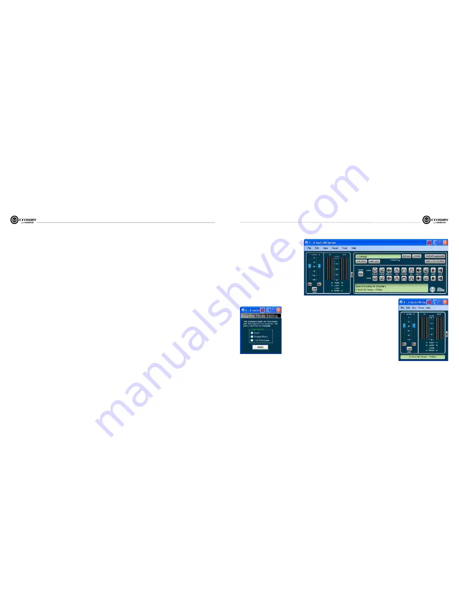
4.8.1 Amplifier DSP Selection Screen
On the left of this screen is the Input Signal Level Monitor
(explained later on this page). On the right side are rows of DSP
selection buttons for each channel. When you click on a button, a
control panel opens for that button’s function.
Also on the right are buttons that open control panels for these
functions:
• Amplifier mode (dual, bridge-mono, input Y)
• Signal generator (pink noise and sine wave)
• Amplifier information
• Recall and store presets
• Preset manager
• Apply to others (apply this amplifier’s DSP settings to other
devices)
We’ll explain each of these functions on the next several pages.
4.8.2 Amplifier Mode
This is switchable between dual, bridge-mono and 1x2 (input Y).
4.8.3 Input Level, Mute, Link, Level Meters, and Indicators
This panel is on the left side of the I-Tech main control panel shown above. Channel 1 and 2 Level
Controls set the input signal level of each channel. Each channel can be muted, and both faders
can be linked with the Link button.
Input Signal Level Meter
The measure ment range is from 0dBFS to –40dBFS with 0.5dB resolution. Each audio channel
has the following monitors:
• Switched Audio Input:
This meter shows only the switched (selected) audio input after the
Input Audio Router.
• Clip Indicator
Output Signal Level Meter
The mea surement range is from 0 dB to –40 dB with 0.5 dB resolution. The monitors are scaled so
that 0 dB is referenced to the full rated output voltage of the amplifier. The left meter is rms and the
right meter is peak. An output clip indicator is provided.
Indicators
Temp:
Lights if the temperature of the amplifier is too high and the amplifier is near shutdown.
Green: Thermal headroom used up is less than 59%.
Yellow: Thermal headroom used up is 60-80%.
Red: Thermal headroom used up is more than 81%.
Limit:
Lights when the amplifier signal is being limited.
Load:
Lights when the load impedance is out of range.
Ready:
Lights when the amplifier is on and ready to supply power.
4.6 Digital Audio Options (AES/EBU)
Digital audio inputs allow you to keep the amplifier input signals
in the digital domain. Keeping the input signal digital reduces the
number of Dig ital-to-Analog and Analog-to-Digital conversions.
This provides better sound quality and reduces pickup of
electrical interference.
The AES/EBU connector provides the most widely accepted
format. Con nect an AES/EBU signal to the AES/EBU connector on
the rear panel. If the amplifier’s low-voltage power supply is lost
for any reason, the AES input signal goes directly to the AES
output. The amplifier has a digital buffer converter so it will adapt
to any AES sample rate between 32 and 96kHz that is sent to it.
4.7 Networking the Amplifier
If you need help understanding network concepts, please see
Appendix A on Network and CobraNet Basics. Please check the
System Architect help file for directions on how to use its
networking configuration tools.
An I-Tech HD amplifier may be used in an existing I-Tech network
and can use existing I-Tech device or venue files.
You can make the following settings via the front panel or by
using the Network Troubleshooter:
HiQnet node address
DHCP off/on
IP address
Subnet mask
You cannot set the CobraNet IP address via the front panel.
4.7.1 Network Troubleshooter
The network troubleshooter can assist you in setting up your
HiQnet network for the first time. Using the troubleshooter, you
can address your components and be informed of addressing and
other errors in the system. Please note that this wizard is designed
to work with devices that are on the same physical network
segment as the computer it is running on. It will not work through
a router.
Select Network Card
The first page of the wizard lists all the network adapters currently
in the computer. If you have more than one adapter, you can scroll
through the list and see the
IP Address
assigned to each card.
If you have a card with an IP address of 0.0.0.0, it typically means
one of several things:
1. The card is disabled.
2. The card is not connected to a network.
3. The card is setup to obtain its address from a DHCP server, and
no DHCP server is available.
Select the card that is connected to the HiQnet system and click
the
Next
button. The Wizard will walk you through the rest of the
process. Please see the System Architect online help for more
information.
4.8 Software-Controllable Onboard DSP
Crown’s latest-generation Digital Signal Processing is built into
the I-Tech HD amplifier. Its 24-bit/96kHz converters offer
extremely low noise and extended dynamic range. When you use
an I-Tech HD amp, the loud speaker processors, crossovers,
limiters and delays are in the onboard DSP – so you don’t need
those rack-mounted devices. This drastically cuts setup time,
commissioning, rack space and costs.
The I-Tech HD’s DSP can be monitored and controlled with a
computer running System Architect software, and connected to
the amplifier Network Connector by a network Category 5 cable.
Some applications for this DSP are:
• Set up signal flow
• Optimize system gain structure
• Set up speaker configurations (set the drive levels, frequency
bands, delays and limiting for your particular speakers)
• Set up EQ, filtering, compression, and much more.
The next several pages explain some of the available DSP
functions. See the System Architect Help files for more detailed
information.
4 Advanced Operation
4 Advanced Operation
Содержание I-T12000 HD
Страница 31: ......


