background image

RADIANT PANEL OR OTHER “LOW TEMPERATURE” SYSTEM

The First Hour Ratings published in this manual are based on a boiler supply temperature of 180F. If, for

any reason, the boiler water temperature going to the heating system is held to levels under 180F, special piping
is needed to provide boiler water to both the Maxi-Therm and the heating system at the proper temperatures.
Two ways of doing this are with a heat exchanger or a 4-way valve.

In either system, the Maxi-Therm must be connected to the boiler before any means are used to control the

temperature of the water going to the system. The temperature of the water going through the Maxi-Therm coil
is thus limited only by the boiler high limit setting, which should be set at 180F or higher.

Figure 9 illustrates the use of a heat exchanger to control the temperature of the water going to the “low

temperature” system. The low temperature system water is completely isolated from the water passing through
the boiler and Maxi-Therm. For this reason, the low temperature system must be equipped with its own
expansion tank, fill, and air removal apparatus. The temperature in this system may be controlled through the
use of an aquastat in the low temperature side.

Figure 10 illustrates the use of a 4-way valve to control maximum heating zone temperature while allowing

180F boiler water to enter the Maxi-Therm zone. The four way valve may be manually set to provide the
maximum allowable temperature to the heating zone or it may be provided with a motor to control the valve in
response to some parameter (outdoor temperature for example).

MAXI-THERM MANIFOLD PIPING (BOILER SIDE)

Multiple Maxi-Therm installations must be done in the “reverse-return” manner illustrated in Figure 11. The

reason for this is to create the same pressure drop (and therefore the same flow) through the coil of each Maxi-
Therm. The boiler manifold piping must be sized so that each coil has the flow rate called for in Table 1. For
example, if two MT040G’s are to be manifold together, the circulator and zone piping common to both tanks
must be capable of moving 16 GPM (2 x 8 GPM)

Because the pressure drop through Maxi-Therm coils varies from size to size, it is hard to predict the flow

rate that will be developed through each coil when two Maxi-Therms of different sizes are placed in the same
manifold. For this reason it is best not to mix Maxi-Therms of two different sizes in the same zone.

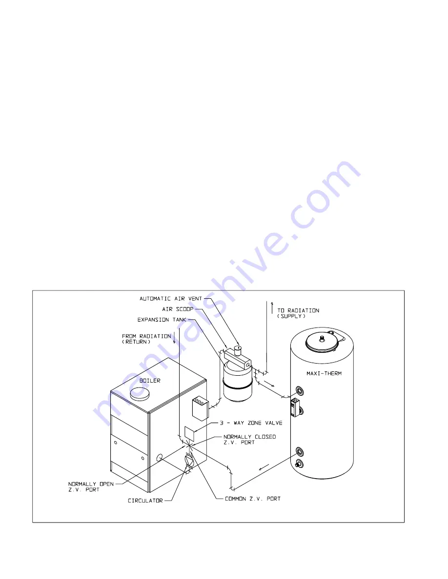
Figure 8: Boiler-Side Piping a 3-Way Zone Valve

22

Содержание MAXI-THERM MT040G

Страница 1: ...Glass Lined Indirect Water Heater INSTALLATION AND OPERATING INSTRUCTIONS WARNING Improper installa tion adjustment alteration service or maintenance can cause property damage injury or loss of life...

Страница 2: ...Residential 5 Detailed Residential 6 Commercial 9 Zone Design 15 IV Before Starting Installation 18 V Locating the Maxi Therm 18 VI Piping 20 Boiler Side 20 Domestic Side 24 VII Wiring 30 VIII Start u...

Страница 3: ...cal authority having jurisdiction before installing an MT079G or MT100G with a boiler having a total gross output in excess of 200 000 BTU hr 2 MT040G MT050G MT079G MT100G FIRST HOUR RATING Gal hr 192...

Страница 4: ...3 Figure 1b MT079G and MT100G General Configuration Figure 1a MT040G and MT050G General Configuration...

Страница 5: ...RIETY OF DEMAND SITUATIONS ENCOUNTERED IN THE FIELD CROWN BOILER COMPANY CANNOT GUARANTEE THE SUITABIL ITY OF THESE PROCEDURES TO ALL INSTALLATIONS Three steps must be taken to properly design a Crown...

Страница 6: ...If a new boiler is to be installed with the Maxi Therm first find a boiler that will handle the space heating load alone If this boiler has an output GREATER than that shown in column f do not add any...

Страница 7: ...Install the Maxi Therm with a boiler having the larger of these two outputs 6 If the Maxi Therm is to be installed with an existing boiler a Go to Table 1 and select a Maxi Therm which has a 135F Fir...

Страница 8: ...2 000 BTU hr output a b c d Shower 3 GPM Head 21 0 X 5 GPM Head 35 0 X 7 GPM Head 49 0 X Bath 30 Gal Tub 21 0 X Vanity 2 8 X Clothes Washer 48 0 X Dishwasher 15 0 X BTU hr BTU hr 1 Boiler Output Requi...

Страница 9: ...Therm 2 Boiler Output Required for Space Heating Select a boiler with an Output equal to 1 or 2 whichever is GREATER 10 0 Peak Hour Demand Total Column d Peak Hour Demand X 1 20 Adjusted Peak Demand K...

Страница 10: ...usage pattern Consult the machine manufacturer and the building owner for this information Once the maximum hourly usage is known for this equipment enter it in the spaces provided under Column 3 g Ad...

Страница 11: ...Crown does not recommend the use of a Maxi Therm to generate 180F water for commercial dishwashers Use the Maxi Therm to generate 135F water and a pre heater to raise the water temperature for the di...

Страница 12: ...Fixtures in Various Types of Buildings 1 2 3 Fixture Description Basins Private Lavatory X Basins Public Lavatory X Bathtubs X Showers X Circular Wash Sinks X Semi Circular Wash Sinks X Foot Basins X...

Страница 13: ...ial Kitchen Fixtures Vegetable Sink 45 X Single Pot Sink 30 X Double Pot Sink 60 X Triple Pot Sink 90 X Bar Sink 30 X 1978 X 0 25 494 5 0 100 594 5 Adjusted Probable Maximum Demand WORKSHEET 2 COMMERC...

Страница 14: ...000 200000 BOILER OUTPUT BTU hr FIRST HOUR RATING GAL hr Figure 4c MT079G Ratings at Different Boiler Outputs 0 50 100 150 200 250 0 50000 100000 150000 BOILEROUTPUT BTU hr FIRST HOUR RATING GAL hr Fi...

Страница 15: ...3 MT100G Time min Ind Ind 10 6 8 4 5 7 4 0 200038 Gallons 79 3 75 2 68 1 59 4 Notes 2 Gallons The total volume of water drawn from the tank during this time 4 All valves shown are approximate 3 Ind D...

Страница 16: ...e fitting pressure drops in column 2 For MT079G and MT100Gs use the fitting pressure drops in column 3 c For each fitting multiply the quantity of the fitting in column 1 by the appropriate pressure d...

Страница 17: ...Std Ball Valve 0 12 0 19 1 1 4 Std Ball Valve 0 06 0 09 1 1 2 Std Ball Valve 0 02 0 03 Taco Flo Chek 220 1 2 18 3 41 220 1 1 4 0 84 1 31 222 1 1 2 0 44 0 69 Taco Air Scoop 431 1 0 15 0 23 432 1 1 4 0...

Страница 18: ...e 0 01 0 02 1 Branch in Tee 0 26 0 41 1 1 4 Branch in Tee 2 0 08 0 13 0 16 1 1 2 Branch in Tee 0 05 0 08 1 Std Ball Valve 0 12 0 19 1 1 4 Std Ball Valve 0 06 0 09 1 1 2 Std Ball Valve 0 02 0 03 Taco F...

Страница 19: ...es Also note that some jurisdictions may not permit the installation of an MT079G or MT100G with a boiler having a gross output in excess of 200 000 BTU hr Consult the authority having jurisdiction be...

Страница 20: ...rther the Maxi Therm is from the boiler the longer the response of the boiler will be to a call from the Maxi Therm zone If long runs exist between the boiler and Maxi Therm it is advisable to insulat...

Страница 21: ...of prioritizing the Maxi Therm In this system a 3 way zone valve is used which has a common port a normally open port and a normally closed port The zone valve motor is wired so as to be energized by...

Страница 22: ...Figure 6 Boiler Side Piping Using Circulator Zones Figure 7 Boiler Side Piping Using Zone Valves 2 Way 21...

Страница 23: ...may be controlled through the use of an aquastat in the low temperature side Figure 10 illustrates the use of a 4 way valve to control maximum heating zone temperature while allowing 180F boiler water...

Страница 24: ...23 Figure 9 Boiler Side Piping in a Low Temperature System Using a Heat Exchanger Figure 10 Boiler Side Piping in a Low Temperature System Using a Mixing Valve...

Страница 25: ...red by some codes Use to prevent water from backing out of the Maxi Therm in the event that inlet water pressure drops d Expansion Tank required when a backflow preventer is used This expansion tank a...

Страница 26: ...This Valve must comply with the Standard for Relief Valves and Automatic Gas Shutoff devices for Hot Water Supply Systems ANSI Z21 22 No valve is to be placed between the T P valve and the Maxi Therm...

Страница 27: ...low towards the Maxi Therm inlet only When no fixtures are drawing water the bronze circulator moves hot water from the Maxi Therm to end of the branch just below the last fixture then back to the inl...

Страница 28: ...Figure 12 Basic Domestic Side Piping Figure 13 Domestic Side Piping Using a Mixing Valve 27...

Страница 29: ...Figure 14a Domestic Side Piping Using a Recirculation Line MT040G MT050G 28 Figure 14b Domestic Side Piping Using a Recirculation Line MT079G MT100G Insulate dashed piping Insulate dashed piping...

Страница 30: ...Figure 15 Domestic Side Piping for Multiple Maxi Therms 29...

Страница 31: ...center consists of a DPDT relay and a 24 volt transformer The Maxi therm control is connected to terminals R and G so that when the Maxi therm control calls for heat the relay is energized One set of...

Страница 32: ...Figure 16 Non Priority Circulator Zoning Using Honeywell R845a s Figure17 PriorityCirculatorZoning 31...

Страница 33: ...become made which energizes the Maxi Therm zone valve The Maxi Therm zone valve opens and its endswitch brings on the boiler If four or fewer zones including the Maxi Therm zone are present the transf...

Страница 34: ...3 Figure 19 ZoneValve Wiring 2 Way Priority Note Connect Zone Valve Port A to Maxi Therm Port B to Heating Zone AB to boiler return Figure 20 Zone Valve Wiring 3 Way Priority Using Honeywell V8044E110...

Страница 35: ...wiring is present 4 Turn off the burner 5 Make sure that each zone valve or circulator operates when and only when its thermostat calls for heat Let each zone operate long enough to purge any remaini...

Страница 36: ...ion This anode rod should be inspected periodically and replaced if more than half of the anode has been corroded away at any point in its length The rate at which the anode rod will deteriorate will...

Страница 37: ...Have the maintenance outlined in Part IX of this manual preformed on an annual basis Also make sure that the boiler is maintained in accordance with its manufacturer s instructions 2 If the temperatur...

Страница 38: ...0000 1 4 O U T ER G A SK ET 220001 1 5 IN N ER G ASK ET 220002 1 6 M 10 x 30m m CARRIA G E B O LT 900023 6 7 M 10 FLAT W ASH ER 90 024 6 8 M 10 H EX N U T 90 025 6 9 CAP 220020 1 9a CAP IN SU LA T IO...

Страница 39: ...005 1 4 CLEAN OUT GASKET 220006 1 5 M12 x 30mm CAP SCREW 900020 8 6 ANODE ROD MT079G 220011 1 6 ANODE ROD MT100G 220012 1 7 JACKET WRAPPER MT079G 220079 1 7 JACKET WRAPPER MT100G 220100 1 8 TOP INSULA...

Страница 40: ...rlpool tub no significant amount of hot water may be used for other purposes while the whirlpool is filling or for a period equal to the recovery time before the whirlpool is filled Also hot water may...

Страница 41: ...Tel 215 535 8900 Fax 215 535 9736 www crownboiler com Manufacturer of Hydronic Heating Products P O Box 14818 3633 I Street Philadelphia PA 19134 Rev 2 05 03...

Отзывы: