pre 1 cycles of 3.2ns. For level triggering, packet length is data dependent
(Figure
on page
Please note that triggering is not accurate to sample. For each 3.2ns clock cycle, it is deter-
mined whether on any sample during that clock cycle a trigger condition is met. The clock cycle
is then selected as the trigger point. As a result, the trigger sample can be anywhere within a
range of up to 16 samples in single channel mode (Figure
on page
) at 16 samples per
3.2ns.
If retriggering is active, the current trigger window is extended if a trigger event is detected
inside the window.
A trigger block can use several input sources:
the 8 trigger decision units of all four ADC channels (Figure
on page
the GATE input (Figure
on page
the Trigger input (Figure
on page
a function trigger providing random or periodic triggering (Section
on page
triggers originating from other cards connected with the sync cable or from the Ndigo
Extension card (BUS0, BUS1, BUS2, BUS3)
A second set of trigger units for the digital inputs Trigger, GATE, BUS0, BUS1, BUS2,
and BUS3 that is set in hardware to positive edge triggering. This set of triggers is not
available as inputs for the gate blocks.
Trigger inputs from the above sources can be concatenated using logical “OR” (Figure
on page
) by setting the appropriate bits in the trigger blocks source mask.
Triggers can be fed into the gate blocks described on page
(Figure
). Gate blocks can
be used to block writing data to the FIFO. That way, only zero suppressed data occurring when
the selected gate is active is transmitted. This procedure reduces PCIe bus load even further
(Figure
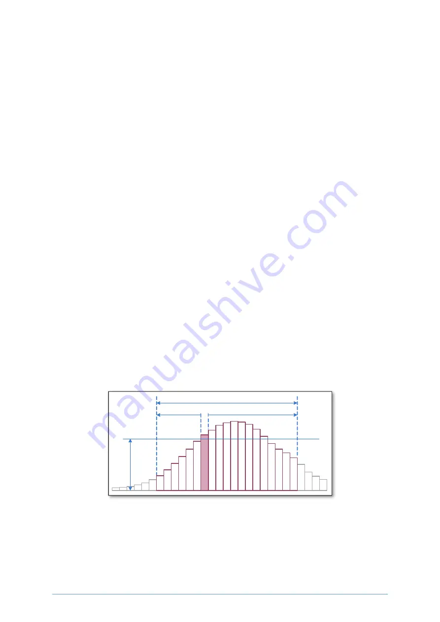
precursor = 6
length = 12
total length = 19
th
re
sh
o
ld
Figure 2.11: Parameters for edge triggering
cronologic GmbH & Co. KG
11
Ndigo5G User Guide
Содержание Ndigo5G-10
Страница 2: ......
Страница 3: ......
Страница 7: ......
Страница 45: ...cronologic GmbH Co KG 40 Ndigo5G User Guide...
Страница 54: ...on page 47 cronologic GmbH Co KG 49 Ndigo5G User Guide...


