CRESTRON
10
••
Series 3500 Touchpanels
Operations Guide - DOC. 8108B
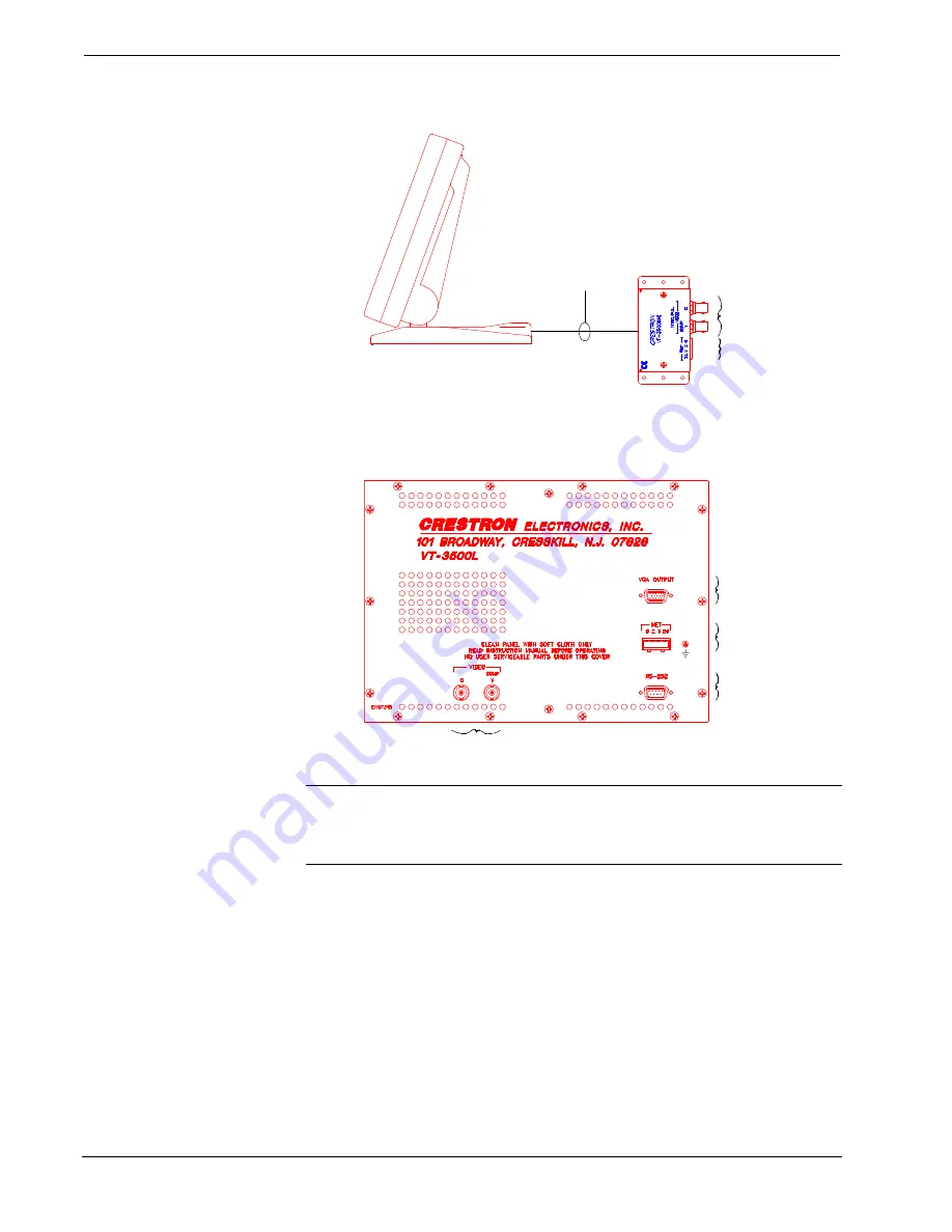
VT-3500 Typical Connection Diagram
CONNECT TO CNMS,
CNRACK, OR CNRACK-D
CONNECT TO
VIDEO SOURCE
Refer to the CRESNET II Network Cable
drawing in this section of the Guide.
SIDE VIEW OF VT-3500
NOTE:
UNITS IN THIS ILLUSTRATION
ARE NOT DRAWN TO SCALE.
CABLE ASSEMBLY
(P/N 15709)
•
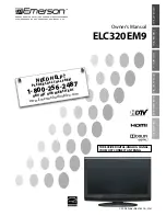
Connect the CT-3500L or VT-3500L directly to the CRESNET II
system via the network cable, shown below.
CT/VT-3500L Typical Connection Diagram
Applies only to VT-3500L.
CONNECT TO VIDEO SOURCE
CONNECT TO SERIAL
PORT OF COMPUTER
Use only for direct connection to PC
to load panels without network.
CONNECT TO CNMS,
CNRACK, OR CNRACK-D
Refer to the CRESNET II Network Cable
drawing in this section of the Guide.
CONNECT TO
ANY VGA DEVICE
(i.e., VIDEO PROJECTOR)
NOTE
Connections shown also apply to the
CT-3500L, except where specified.
NOTE:
Network termination points are available at the control system power
supply. Network units may also be daisy-chained together. Refer to the latest
revision of the CRESNET II reference manual section on CNPWS power supplies
(Doc. 8091) for wire gauge specifications and connection details.
3. This step only applies to video windows (VideoTouch configurations).
If composite video is required, connect video cable to VIDEO COMP
port (composite video input). Otherwise, if S-video is required,
connect chrominance and luminance to VIDEO C and VIDEO Y
ports, respectively. Select appropriate input in the Setup Menu as
described in the Configuring the Touchpanel section.
4. This step only applies to VideoTouch and CT-3500L configurations. If
necessary, connect a VGA device, such a a video projector, to VGA
OUTPUT.
5. Apply power to the touchpanel and observe illumination of the touch-
sensitive screen. The touchpanel enters RUN MODE and displays a


