background image

Wideband RGB Matrix Switcher 


Crestron 

CEN-RGBHV


DHCP Screen 2 (Showing DHCP Set to On) 

        DHCP
*On


Press 

ENTER

 to save the new setting. The display will return to the “DHCP” screen. 

Use the quick-adjust knob to select another Network Setup parameter. The next 
parameter is HostName. 

Network: 
HostName  

“HostName” Screen 

    Network Setup
HostName


To view the host name, press 

ENTER

. The display will show the existing host name. 

HostName Screen 2 

      HostName
RGBHV1


To set up the hostname, press 

ENTER

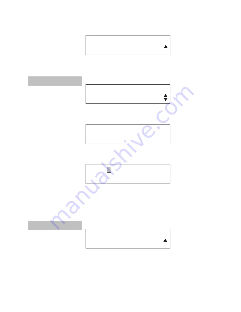
HostName Setup Screen 

RGBHV1
 Del  Ins   <    >


Use the buttons below the 

<

 and 

>

 symbols on the display to navigate to the digit you 

wish to set. Use the buttons below 

Del

 and 

Ins

 to delete and/or insert digits. Change 

a digit by rotating the quick-adjust knob. 

Press 

ENTER

 to save the new setting. The display will return to the “HostName” 

screen. Use the quick-adjust knob to select another Network Setup parameter. The 
next parameter is MAC Address. 

Network: 
MAC Address 


“MAC Address” Screen 

    Network Setup
MAC Address


To display the MAC Address, press 

ENTER

40  

  Wideband RGB Matrix Switcher: CEN-RGBHV 

Operations Guide – DOC. 6612C 

Содержание CEN-RGBHV

Страница 1: ...Crestron CEN RGBHV WidebandRGBMatrixSwitcher Operations Guide ...

Страница 2: ... apparatus has been exposed to rain or moisture does not operate normally or has been dropped Disconnect power prior to connecting or disconnecting equipment Do not install in direct sunlight The apparatus must be installed in a way that the power cord can be removed either from the wall outlet or from the device itself in order to disconnect the mains power Prevent foreign objects from entering t...

Страница 3: ...ion Software Requirements for the PC 22 Programming with Crestron SystemBuilder 22 Programming with SIMPL Windows 22 Example Program 25 Uploading and Upgrading 26 Establishing Communication 26 Programs and Firmware 27 Program Checks 28 Operation 29 Menu Structure 29 Setup and Informational Screens 29 Routing Signals 47 Sync Mode 48 Problem Solving 49 Troubleshooting 49 Check Network Wiring 49 Refe...

Страница 4: ......

Страница 5: ...ers university lecture halls high tech houses of worship command and control facilities and live staging events Features and Functions High bandwidth matrix switcher 8 x 4 in CEN RGBHV8X4 8 x 8 in CEN RGBHV8X8 12 x 4 in CEN RGBHV12X4 12 x 8 in CEN RGBHV12X8 16 x 16 in CEN RGBHV16X16 Low crosstalk with incredibly flat response 450 MHz video bandwidth 3 dB Professional balanced stereo audio Audio in...

Страница 6: ...included 8 x 4 on the CEN RGBHV8X4 8 x 8 on the CEN RGBHV8X8 12 x 4 on the CEN RGBHV12X4 12 x 8 on the CEN RGBHV12X8 and 16 x 16 on the CEN RGBHV16X16 supporting both balanced and unbalanced signals Programmable input level compensation helps ensure compatibility with a wide range of pro and semi pro sources Automatic blanking achieves a pop free transition when switching between sources Every out...

Страница 7: ...etection selectable input termination vertical interval switching using genlock input Signal Types RGB and composite S video or component video does not transcode Video HDTV Formats NTSC or PAL HDTV up to 1080i 1080p RGB Formats RGBHV RGBS RGsB or YUV Gain 0 dB 75 Ω terminated Bandwidth 450 MHz 3 dB fully loaded Blanking Time Adjustable 0 to 10 seconds 0 5 second steps Crosstalk 65 dB 5 MHz 47 dB ...

Страница 8: ...hesive feet and rack ears included Dimensions Height without feet 5 20 in 13 21 cm 10 47 in 26 60 cm CEN RGBHV16X16 only Width without ears 17 03 in 43 24 cm 17 28 in 43 90 cm CEN RGBHV16X16 only Width with ears 19 00 in 48 26 cm Depth 13 10 in 33 26 cm 20 68 in 52 51 cm CEN RGBHV16X16 only Weight CEN RGBHV8X4 CEN RGBHV8X8 CEN RGBHV12X4 CEN RGBHV12X8 15 lbs 6 80 kg CEN RGBHV16X16 40 lbs 18 14 kg 1...

Страница 9: ...cher Physical Description This section provides information on the connections controls and indicators available on your CEN RGBHV CEN RGBHV8X4 Front View CEN RGBHV8X4 Rear View Operations Guide DOC 6612C Wideband RGB Matrix Switcher CEN RGBHV 5 ...

Страница 10: ...Wideband RGB Matrix Switcher Crestron CEN RGBHV CEN RGBHV8X8 Front View CEN RGBHV8X8 Rear View 6 Wideband RGB Matrix Switcher CEN RGBHV Operations Guide DOC 6612C ...

Страница 11: ...Crestron CEN RGBHV Wideband RGB Matrix Switcher CEN RGBHV12X4 Front View CEN RGBHV12X4 Rear View Operations Guide DOC 6612C Wideband RGB Matrix Switcher CEN RGBHV 7 ...

Страница 12: ...Wideband RGB Matrix Switcher Crestron CEN RGBHV CEN RGBHV12X8 Front View CEN RGBHV12X8 Rear View 8 Wideband RGB Matrix Switcher CEN RGBHV Operations Guide DOC 6612C ...

Страница 13: ...Crestron CEN RGBHV Wideband RGB Matrix Switcher CEN RGBHV16X16 Front View Operations Guide DOC 6612C Wideband RGB Matrix Switcher CEN RGBHV 9 ...

Страница 14: ...Wideband RGB Matrix Switcher Crestron CEN RGBHV CEN RGBHV16X16 Rear View 10 Wideband RGB Matrix Switcher CEN RGBHV Operations Guide DOC 6612C ...

Страница 15: ...CEN RGBHV12X4 CEN RGBHV12X8 Overall Dimensions CEN RGBHV12X8 Shown 12 03 in 30 55 cm 13 10 in 33 26 cm 16 17 18 19 20 21 22 23 24 25 16 17 03 in 43 24 cm 5 20 in 13 21 cm 9 10 11 12 13 14 15 1 2 3 4 5 6 7 8 Operations Guide DOC 6612C Wideband RGB Matrix Switcher CEN RGBHV 11 ...

Страница 16: ...GB Matrix Switcher Crestron CEN RGBHV CEN RGBHV16X16 Overall Dimensions 17 28 in 43 90 cm 10 47 in 26 60 cm 19 86 in 50 45 cm 20 68 in 52 51 cm 12 Wideband RGB Matrix Switcher CEN RGBHV Operations Guide DOC 6612C ...

Страница 17: ... Pin 1 Pin 3 Pin 4 1 USB Type B female USB 1 1 computer console port 6 foot cable included PIN DESCRIPTION 1 5 VDC 2 Data 3 Data 4 Ground 10 HW R 1 recessed miniature pushbutton for hardware reset reboots the switcher 11 CLEAR 1 pushbutton red LED clears all matrix routing 12 VIEW 1 pushbutton red LED toggles VIEW mode on off 13 TAKE 1 pushbutton red LED executes routing 14 QUICK ADJUST KNOB 1 con...

Страница 18: ... CEN RGBHV16X16 16 24 or 32 4 DIP switches select input termination for each input independently for H and V sync 18 VIDEO OUT 4 8 or 16 3 sets of 5 BNC female each set comprising 3 high bandwidth video inputs plus 2 sync inputs Output level 0 2 to 5 0 Vp p Output impedance 75 Ω nominal Return loss 30 dB 5 MHz Continued on following page 14 Wideband RGB Matrix Switcher CEN RGBHV Operations Guide D...

Страница 19: ...0 60Hz 1 IEC socket main power input Mates with removable power cord included Dual fuse holder requires 1 20 mm x 5 mm time lag type fuse rated for 2 5 Amps 250 Volts and 1 20 mm x 5 mm time lag type fuse rated for 10 Amps 250 Volts 6 23 G 1 6 32 screw chassis ground lug 24 AUDIO IN 8 12 or 16 2 5 pin 3 5 mm detachable terminal blocks Balanced unbalanced stereo line level inputs Maximum input leve...

Страница 20: ...armful interference and 2 this device must accept any interference received including interference that may cause undesired operation This equipment has been tested and found to comply with the limits for a Class B digital device pursuant to part 15 of the FCC Rules These limits are designed to provide reasonable protection against harmful interference in a residential installation This equipment ...

Страница 21: ...rol Reference Guide Doc 6052 which is available for download from the Crestron website www crestron com manuals Identity Code Net ID The Net ID of the CEN RGBHV has been factory set to 33 The Net IDs of multiple CEN RGBHV devices in the same system must be unique Net IDs are changed from a personal computer PC via the Crestron Toolbox refer to Establishing Communication on page 26 When setting the...

Страница 22: ... rack take special precautions to ensure that the system remains stable The following guidelines are provided to ensure your safety When mounting this unit in a partially filled rack load the rack from the bottom to the top with the heaviest component at the bottom of the rack If the rack is provided with stabilizing devices install the stabilizers before mounting or servicing the unit in the rack...

Страница 23: ...te side Stacking Four feet are provided with the CEN RGBHV so that if the unit is not rack mounted the rubber feet can provide stability when the unit is placed on a flat surface or stacked These feet should be attached prior to the hookup procedure Refer to the following illustration for placement of the feet Foot Placement for the CEN RGBHV PLACE FEET IN CORNERS Operations Guide DOC 6612C Wideba...

Страница 24: ...00 BASE T ETHERNET TO LAN 100 240V 2 0A 50 60 HZ MAIN POWER INPUT GROUND NOTE Ensure the unit is properly grounded Fuse Replacement If the CEN RGBHV does not power up when it is plugged into an AC outlet one or both fuses may need to be replaced The fuse holder is located on the rear panel as the lower section of the IEC socket assembly To replace one or both fuses 1 Disconnect power to the CEN RG...

Страница 25: ...the right side of the fuse holder and should have a value of 10 Amps 250 Volts 4 Inert the fuse holder in the CEN RGBHV and push it inward until it clicks into place 5 Connect power to the CEN RGBHV Label the Buttons Use Crestron Engraver software to print custom labels for the CEN RGBHV s front panel buttons and LEDS Crestron recommends printing on 100 pound paper Paper weighing less than 100 pou...

Страница 26: ... website www crestron com versiontracker Programming with Crestron SystemBuilder Crestron SystemBuilder is the easiest method of programming but does not offer as much flexibility as SIMPL Windows For additional details download SystemBuilder from the Crestron website and examine the extensive help file Programming with SIMPL Windows NOTE While SIMPL Windows can be used to program the CEN RGBHV it...

Страница 27: ... Ethernet Control Modules Ethernet Video Modules folder of the Device Library and drop it in the System Views Locating the CEN RGBHV Ethernet in the Device Library The system tree of the control system displays the device in the appropriate slot with a default Net ID or IP ID as shown in the following illustration Operations Guide DOC 6612C Wideband RGB Matrix Switcher CEN RGBHV 23 ...

Страница 28: ...re assigned different Net ID or IP ID numbers as they are added If necessary double click a device to open the Device Settings window and change the Net ID or IP ID as shown in the following figure CEN RGBHV Cresnet Device Settings Window 24 Wideband RGB Matrix Switcher CEN RGBHV Operations Guide DOC 6612C ...

Страница 29: ... is the view where programmers program a Crestron control system by assigning signals to symbols The symbol can be viewed by double clicking on the icon or dragging it into Detail View Each signal in the symbol is described in the SIMPL Windows help file F1 Example Program An example program for the CEN RGBHV is available from the Crestron website www crestron com exampleprograms Operations Guide ...

Страница 30: ...lish communication between the PC and the control system as described in the latest version of the 2 Series Control Systems Reference Guide Doc 6256 Use the Address Book in Crestron Toolbox to create an entry for the CEN RGBHV using the expected communication protocol Indirect Select the Cresnet ID of the CEN RGBHV and the address book entry of the control system that is connected to the CEN RGBHV...

Страница 31: ...play the CEN RGBHV s System Info window click the icon communications are confirmed when the device information is displayed Programs and Firmware Program or firmware files may be distributed from programmers to installers or from Crestron to dealers Firmware upgrades are available from the Crestron website as new features are developed after product releases One has the option to upload programs ...

Страница 32: ...ernet connections display the System Info window click the icon and select the Functions menu to display actions that can be performed on the CEN RGBHV Be sure to use the Crestron Toolbox to create the CEN RGBHV IP table Select Functions IP Table Setup Add modify or delete entries in the IP table The CEN RGBHV can have only one IP table entry A defined IP table can be saved to a file or sent to th...

Страница 33: ...work Setup IP Address Network Setup Subnet Mask Network Setup Def Router Network Setup DHCP Network Setup HostName Network Setup MAC Address Control Setup Backlight Control Setup Password Control Setup Info Control Setup Defaults Control Setup Front Panel Setup and Informational Screens The following paragraphs describe the various setup and informational screens that are available with the CEN RG...

Страница 34: ...rotary quick adjust knob on the front panel NOTE The and symbols in the lower right corner of the display let you know if there are screens available above and or below the presently displayed screen To exit the Setup Menu screens press the MENU button repeatedly until you see the Exit Setup Menu screen shown on the following page The number of presses required will depend on how deeply into the m...

Страница 35: ...vel for the source connected to input number 1 press the IN button below 1 on the front panel The LED above IN 1 will light and the current gain setting for input 1 will be displayed Input 1 Comp Screen Input 1 Comp 0 0 dB Use the quick adjust knob to change the gain In this example we will raise the gain 0 5 dB The display will show the change in gain along with a bar graph Gain Screen Gain 0 5 d...

Страница 36: ...level In this example we will lower the output level by 1 The display will show the change in output level along with a bar graph Volume Screen Volume 79 Press ENTER to return the display to the Output Volume screen Press ENTER to select another input or use the quick adjust knob to select another Audio Setup parameter The next parameter is Input Names Audio Input Names Input Names Screen Audio Se...

Страница 37: ...the quick adjust knob to select the output you wish to name Then press ENTER Output Name Setup Screen OUT1 Del Ins Use the buttons below the and symbols on the display to navigate to the digit you wish to set Use the buttons below Del and Ins to delete and or insert digits Change a digit by rotating the quick adjust knob Press ENTER to save the new setting The display will return to the Sel output...

Страница 38: ...to the Audio Setup category screen Use the quick adjust knob to select another category The next category is Video Setup Video Setup Video Setup Screen Setup Menu Video Setup Press the ENTER button to select which parameter of the Video Setup menu you wish to view From any of the parameter level menus you can select a different parameter by using the rotary quick adjust knob on the front panel For...

Страница 39: ...hange a digit by rotating the quick adjust knob Press ENTER to save the new setting The display will return to the Sel input to name screen Use the quick adjust knob to select another input or press MENU to return to the Input Names screen From the Input Names screen use the quick adjust knob to select another Video Setup parameter The next parameter is Output Names Video Output Names Output Names...

Страница 40: ...sed to ensure that no flickering occurs on the video output as the new sync signals are sent to the display Audio blanking may be used to mute the audio signal during video blanking Video Video Blanking Video Blanking Screen Video Setup Video Blanking To set video blanking press ENTER Use the quick adjust knob to turn audio blanking on or off Video Blanking Screen 2 Video Blanking Off An asterisk ...

Страница 41: ...ut 1 will be displayed Out 1 Blanking Screen Out 1 Blanking 0 0 sec Use the quick adjust knob to change the blanking time In this example we will change the blanking for output 1 from 0 to 0 5 seconds The display will show the change in blanking time along with a bar graph Blanking Screen Blanking 0 5 sec Press ENTER to save the new setting The display will return to the Blanking Setup screen Pres...

Страница 42: ... IP Address IP Address Screen Network Setup IP Address To set the IP address press the ENTER button IP Address Screen 2 IP Address 123 456 789 000 Use the quick adjust knob to set the values for the first three digits in the IP address Then press ENTER to move the brackets to the next three digits and use the quick adjust knob to set the values for these Use the ENTER button and quick adjust knob ...

Страница 43: ...he default router press the ENTER button Def Router Screen 2 Def Router 123 456 789 000 Use the quick adjust knob to set the values for the first three digits in the default router Then press ENTER to move the brackets to the next three digits and use the quick adjust knob to set the values for these Use the ENTER button and quick adjust knob to set the values for next two groups of three digits P...

Страница 44: ...1 To set up the hostname press ENTER HostName Setup Screen RGBHV1 Del Ins Use the buttons below the and symbols on the display to navigate to the digit you wish to set Use the buttons below Del and Ins to delete and or insert digits Change a digit by rotating the quick adjust knob Press ENTER to save the new setting The display will return to the HostName screen Use the quick adjust knob to select...

Страница 45: ...he front panel For example pressing the ENTER button from the Control Setup menu will display one of the following parameters Backlight Password Info Defaults Front Panel Using the quick adjust knob you can change to any of the other parameters of the Control Setup menu When you see the parameter you wish to enter press the ENTER button Control Backlight Backlight Screen Control Setup Backlight To...

Страница 46: ...ow the and symbols on the display to navigate to the digit you wish to set Use the buttons below Del and Ins to delete and or insert digits Change a digit by rotating the quick adjust knob Press ENTER to save the new setting The display will return to the Password screen Use the quick adjust knob to select another Control Setup parameter The next parameter is Info Control Info Info Screen Control ...

Страница 47: ...e information The actual screen displays will require scrolling to see all the information Use the quick adjust knob to view other hardware information parameters or press MENU to return to the Info HW OPS screen FLASH Screen FLASH Flash Monitor Screen Monitor 64 KB 64 KB 100 Flash Code Screen Code 458 KB 1984 KB 23 Flash File System Screen File System 68 KB 6144 KB 1 TOTAL FLASH Screen TOTAL FLAS...

Страница 48: ...RAM Code Screen Code 458 KB 2153 KB 21 RAM Initialized Data Screen Initialized Data 6 KB 2153 KB 0 RAM Uninitialized Data Screen Uninitialized Data 1684 KB 2153 KB 0 RAM Heap Screen Heap 534 KB 28566 KB 1 RAM File System Screen File System 0 KB 2048 KB 0 44 Wideband RGB Matrix Switcher CEN RGBHV Operations Guide DOC 6612C ...

Страница 49: ... parameter is Defaults Control Defaults Defaults Screen Control Setup Defaults To reset factory defaults press ENTER Use the quick adjust knob to select whether to restore defaults for Audio settings only Video setting only All settings or select Abort to maintain the current settings Defaults Screen 2 Showing Audio settings only Option Restore Defaults Audio settings onl An asterisk to the left o...

Страница 50: ...ameter is Front Panel Control Front Panel Front Panel Screen Control Setup Front Panel To turn the front panel lock on or off press ENTER Use the quick adjust knob to set the front panel lock on or off Front Panel Screen 2 Front Panel Lock Off An asterisk to the left of the front panel lock option will show the current setting Press ENTER to save the new setting The display will return to the Fron...

Страница 51: ...W mode its LED will light and the unit will display the video routing Pressing the VIEW button again will toggle the unit to ROUTE mode In ROUTE mode the LED above the VIEW button will not be lit The display will show the Route Mode screen Route Mode Screen Route Mode Press input outputs If the A button is pressed its LED will light and you can route audio signals If the V button is pressed its LE...

Страница 52: ...the IN button below 1 on the front panel The LED above IN 1 will light and the sync rates for input number 1 will be displayed Sync Screen Showing Horizontal and Vertical Sync Rates for Input 1 1HSync 63897Hz 1VSync 60Hz To refresh the current rate press the numbered IN button below the selected input again A displayed sync rate of 0 Hz indicates that no sync has been detected To view the sync rat...

Страница 53: ...en daisy chaining Cresnet units strip the ends of the wires carefully to avoid nicking the conductors Twist together the ends of the wires that share a pin on the network connector and tin the twisted connection Apply solder only to the ends of the twisted wires Avoid tinning too far up the wires or the end becomes brittle Insert the tinned connection into the Cresnet connector and tighten the ret...

Страница 54: ...ime users will need to establish a user account to fully benefit from all available features Future Updates As Crestron improves functions adds new features and extends the capabilities of the CEN RGBHV additional information may be made available as manual updates These updates are solely electronic and serve as intermediary supplements prior to the release of a complete technical documentation r...

Страница 55: ...or 90 days batteries and incandescent lamps are not covered This warranty extends to products purchased directly from CRESTRON or an authorized CRESTRON dealer Purchasers should inquire of the dealer regarding the nature and extent of the dealer s warranty if any CRESTRON shall not be liable to honor the terms of this warranty if the product has been used in any application other than that for whi...

Страница 56: ...Crestron Electronics Inc Operations Guide DOC 6612C 15 Volvo Drive Rockleigh NJ 07647 2019030 Tel 888 CRESTRON 09 08 Fax 201 767 7576 Specifications subject to www crestron com change without notice ...

Отзывы: