Loop Mode
Loop Mode is an extension of trigger mode and utilizes all the same feature set.
To create the loop, the function generator uses the end of decay trigger (F TRIG
JACK) created at the end of the cycle to retrigger the attack creating a voltage
controllable low frequency oscillator and clock source.
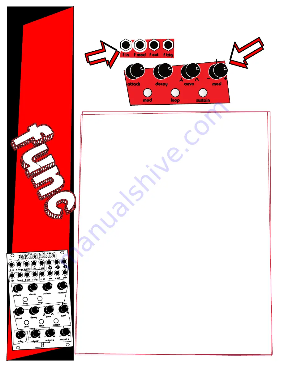
Response Curve
The CURVE KNOB determines the linearity of the attack and decay stages from
exponential through linear to logarithmic. Turning the CURVE KNOB full left creates
a exponential response. At 12 o’clock the response is linear. Turning the CURVE
KNOB beyond 12 o’clock creates an logarithmic response.
Voltage Controlled Attack and Decay Times
Voltage control over the attack time, decay time, and both attack and decay
times is available. A CV signal can be patched to the F MOD JACK. This signal is
passed through the MOD KNOB.
The MOD KNOB is an attenuverter. That means the incoming signal is off when the
trimmer is set to the 12 o’clock position. Turning the attenuverter to the right
passes the original signal through. Turning the attenuverter to the left passes an
inverted version of the original signal through. Locating the exact off position of
an attenuverter can be difficult. The easiest way to remove the CV signal from
the signal path is to simply remove the patch cable patched into the F MOD
JACK or deselect attack and decay using the MOD BUTTON.
The MOD BUTTON sets the attenuverted modulation destination. The modulation
destination can be set to attack, decay, both attack and decay, or off.
Function Generator
(4 of 4)
2
and
O
ut
s
Ins
and
Buttons
Knobs


