background image

10

Crathco

®

Model 3311 Beverage Freezer

Cleaning and Maintenance (continued)

Disassembly and Cleaning

NOTICE:

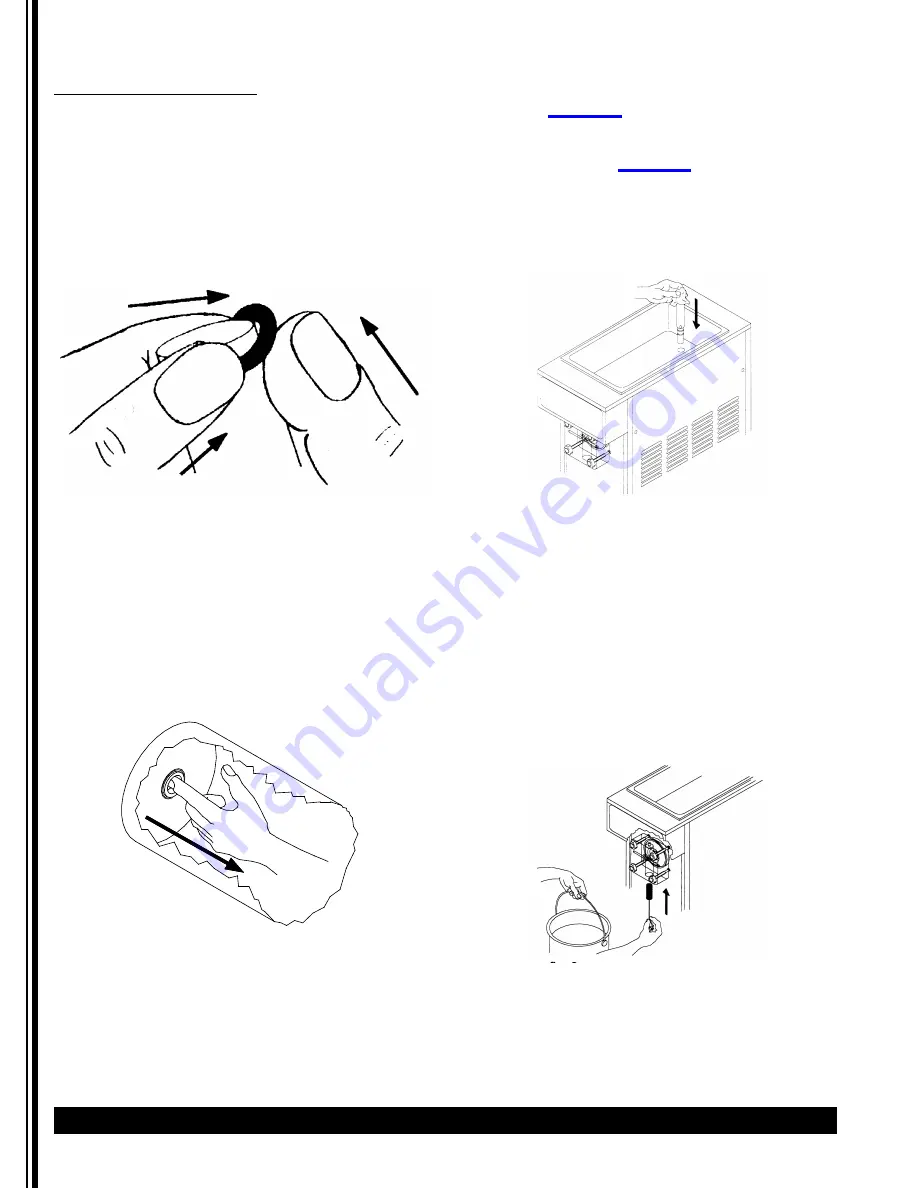
The best way to remove an O-ring is to first

wipe off all of the lubricant using a clean paper towel.
Pinch the O-ring upward with a dry paper towel
between your index finger and thumb. When a loop is
formed in the O-ring, roll it out of the groove with your
other thumb. Always remove the O-ring farthest from
the end of the plunger first. Be careful not to pull or
tug excessively on O-rings. O-rings can be distorted and
will deteriorate sealing performance.Carefully inspect
the O-rings and replace if necessary. (See Figure Q)

3.  Remove the dasher assembly from inside the

freezing cylinder taking care to avoid damaging
the rear seal assembly at the back of the
freezing cylinder. Disassemble the dasher
assembly by removing the stator rod and front
and rear stator rod bearings.

4.  Remove stationary half of the shaft seal

assembly from the back end of the freezer
cylinder. This is accomplished by reaching into
the cylinder and pulling seal out with your
index finger. (See Figure R)

5.  Slide the rotary half of the seal off the dasher

shaft. Inspect both seal components carefully
for nicks or cracks. Replace seal if defective.

NOTICE:

To prevent leakage the surfaces of the rotary

seal and the stationary seal must be smooth with no
chips or cracks.

NOTICE:

All units are shipped with a standard ceramic

seal (Part #

 W0340201

) unless otherwise specified.

Certain products contain coconut oil which requires a
different sealing material. For these products use the
coconut oil seal (Part # 

W0340210

). The stationary half

of the standard seal has a white polished surface. The
stationary half of the coconut oil seal has a glossy black
surface.

6.  Remove carb tube from bottom of hopper and

remove O-rings. (See Figure S).

7.  Remove drip tray and empty contents.
8.  Take all components to the cleaning area.
9.  Prepare 1 gallon solution of hot tap water and

common dishwashing detergent.

10.  Thoroughly wash all components in a warm,

mild detergent solution including the inside of
the freezing cylinder and the mix storage
hopper. 

DO NOT WASH COMPONENTS IN A

DISHWASHER.

11.  Use a medium sized brush to clean the bottom

of the valve body and the inside of the plunger
bore with detergent solution taking care to
remove only remaining lubricant. (Figure T)

12.  The exterior of the freezer should be cleaned as

needed with a cloth towel.

NOTICE:

Coarse rags, abrasive cleaners

and excessive force can damage and/or
scratch the surfaces of the freezer.

Figure Q 

Ring Removal

Figure R 

Removal of stationary half of seal

Figure S 

Carb Tube

Figure T 

Clean Valve Body

Содержание Standard 3311

Страница 1: ...ring Diagram and Parts List 27 Wiring Diagram 30 Ladder Diagram 31 Spinner Hook Up 34 Refrigeration Diagram and Parts List 35 Refrigeration Schematic 38 Thank you for purchasing this quality beverage...

Страница 2: ...ot put objects or fingers in the dispense plunger Read and understand the operating instructions in this manual thoroughly Only allow properly trained persons to operate this machine Do not wear loose...

Страница 3: ...Start 1 2 hp Capacitor Start 1 2 hp Capacitor Start Compressor 3 4 hp 3 4 hp 3 4 hp Cooling Air cooled Air cooled Water cooled Actual Weight 175 lbs 79 4 kg 175 lbs 79 4 kg 175 lbs 79 4 kg Mix Hopper...

Страница 4: ...ain alcohol have a tendency to separate or stratify Separation of product on the mix storage hopper can result in frozen product quality inconsistency Simply keeping the product in the mix storage hop...

Страница 5: ...DAMAGE IN TRANSIT WHETHER VISIBLE OR CONCEALED DO NOT PAY THE FREIGHT BILL until the freezer has been checked for damage Have the carrier note any visible damage on the freight bill If concealed damag...

Страница 6: ...on cord WARNING Do not alter or deform the plug in any way Altering or deforming the plug may cause electrical shock damage unit and will void warranty 13 Remove the drip tray kit from the bubble wrap...

Страница 7: ...d monitoring system to maintain the mix hopper level Private Label Header A private label or different drink header can be installed by removing two screws from the electrical box cover Place the head...

Страница 8: ...cy Adjustment From time to time it may become necessary to readjust the consistency setting thickness to compensate for variation between different mixes or to switch from one type of product to anoth...

Страница 9: ...e front dispensing valve and drain all product from the freezer Close the dispensing valve and turn freezer to OFF NOTICE Use approximately 2 gallons 10 liters of cool water to rinse product out of fr...

Страница 10: ...al if defective NOTICE To prevent leakage the surfaces of the rotary seal and the stationary seal must be smooth with no chips or cracks NOTICE All units are shipped with a standard ceramic seal Part...

Страница 11: ...the seal must be completely dry before reassembling If the circular half of the seal is white make sure that the grooved side is toward the rubber If the circular half is black be sure the glossy sid...

Страница 12: ...bricant onto a piece of clean paper towel Use a clean piece of paper towel to pick up the small end of the valve plunger assembly Apply a thin film of lubricant from the other piece of paper towel Fig...

Страница 13: ...mix storage hopper with fresh product Cover hopper with hopper lid 19 Turn front panel switch to ON Allow the freezer to reach proper consistency Clean In Place Procedure Daily Cleaning This equipmen...

Страница 14: ...nths Every 6 Months Annually Quantities to be Replaced Shaft Seal W0340201 or W0340210 Replace 1 Drive Shaft W0451067 Inspect replace if necessary 1 Drive Belts W0450209 Inspect replace if necessary 1...

Страница 15: ...r blades for wear if equipped replace once per year minimum Check dasher for signs of wear replace if necessary Verify alignment when replacing Check valve body gasket for wear replace once per year m...

Страница 16: ...han 1 2 the motor will need to be lowered If the deflection is less than 1 2 the motor will need to be raised Follow this procedure to adjust the motor to achieve proper belt tension See Figure FF 1 U...

Страница 17: ...clogged Drive belt broken or off pulley Drive shaft worn Drive motor failure Turn power switch ON Refill hopper Readjust consistency setting Unclog carburetor inlet hole Repair or replace Inspect squ...

Страница 18: ...th Shiny Side CHECK LIST PARTS IDENTIFICATION Coconut Oil Seal W0340210 and Standard Seal W0340201 include 1 2 3 Slush Plunger W0480438 Thick Product Plunger W0480451 W0430026 Scraper Blade Dasher W04...

Страница 19: ...6 W0472064 Drip Pan Bracket 12 W0450053 Pulley 10 37 W0430026 Dasher Standard 13 W0450209 Belt V 38 W0430032 Stator Flange Bearing 14 W0572202 Electrical Box Assembly 39 W0520063 Rear Machine Panel 15...

Страница 20: ...ANTY CARD 32 W0641027 DRAIN TUBE HOSE 9 W0800162 PACKAGING ASSEMBLY 33 W0570941 MIX LOW IND FLOAT 10 W0890218 DRIP PAN KIT 34 W0340055 SQUARE CUT O RING 11 W0430026 STANDARD DASHER 35 W0480450 VALVE B...

Страница 21: ...31205 COMPRESSION SPRING 12 W0340022 O RING 213 38 W0480451 PLUNGER THICK PRODUCT 13 W0470076 LUBRICANT LUBRIFILM SANITARY 39 W0200180 CONDENSER ASSEMBLY 14 W0480438 PLUNGER STANDARD PRODUCT 40 W04500...

Страница 22: ...INT TOOTH LK WSHR 90 W0611074 1 4 20 HEX NUTS 100 W0611082 5 16 18 FLANGE NUT 110 W0200412 COMPRESSOR SPACER 120 W0200413 COMPRESSOR GROMMET ITEM PART NUMBER DESCRIPTION ITEM PART NUMBER DESCRIPTION...

Страница 23: ...TION 10 W0210083 FRAME ASSEMBLY 70 W0611410 RIVET MAGNA LOCK 20 W0201007 COMPRESSOR ASSEMBLY 80 W0611247 1 4 INT TOOTH LK WSHR 30 W0201002 CONDENSER ASSEMBLY 90 W0611074 1 4 20 HEX NUTS 40 W0321040 FA...

Страница 24: ...ooled Model ITEM PART NUMBER DESCRIPTION 10 W0210068 BASE PAN 20 W0201001 COMPRESSOR ASSEMBLY 30 W0321026 DRIVE MOTOR ASSEMBLY 40 W0210083 FRAME ASSEMBLY 50 W0611410 RIVET MAGNA LOCK 60 W0611082 5 16...

Страница 25: ...6 32 X 1 4 SCREW 11 W0610131 8 32 X 1 4 SCREW 12 W0610015 6 32 X 1 4 SCREW 13 W086827 6 32 HEX NUT 14 0076 SCRW 8 X 3 8 SL IHWH TYP 23 15 83151 WASHER LOCK 8 EXT TOOTH 16 W0630006 HEYCO SNAP BUSHING...

Страница 26: ...667 RUN CAPACITOR 190 W0610131 8 32 X 1 4 SCREW 60 W0570666 START CAPACITOR 200 W0570876 COMPRESSOR RELAY 70 W0570651 HEAT SEQUENCER 210 W0572192 MIX LOW WIRE SUB ASSY 80 WO630812 CLIP CAPACITOR 230 W...

Страница 27: ...B ASSY 38 W0570651 TIME DELAY RELAY 39 W0570235 TERMINAL BLOCK 40 W0570603 START CAPACITOR 41 W0570617 RUN CAPACITOR 42 W0572192 MIX LOW SUB ASSY 43 W0572068 POWER CORD 44 W0630801 TIE WRAPS 45 W05700...

Страница 28: ...DESCRIPTION 47 W0570635 CONTACTOR RELAY 48 W0570651 TIME DELAY RELAY 49 W0571051 TOGGLE SWITCH 50 W0570235 TERMINAL BLOCK 52 W0570871 TRANSFORMER 53 W0570018 INDICATOR LIGHT 55 W0570667 RUN CAPACITOR...

Страница 29: ...0570603 START CAPACITOR 47 W0570043 FLORESCENT LIGHT BULB 39 W0570235 TERMINAL BLOCK 46 W0570044 LIGHT SOCKET 38 W0570651 TIME DELAY RELAY 45 W0570045 CORE COIL BALLAST 37 W0572032 TRANSFORMER SUB ASS...

Страница 30: ...Wiring Diagram Compressor Wiring 115V Air Cooled Model 220V Air Cooled Model 115V Water Cooled Model START CAPACITOR RUN CAPACITOR COMPRESSOR RELAY RED RED RED RED RED RED RED BLACK BLACK YELLOW WIRES...

Страница 31: ...Model 3311 Beverage Freezer Crathco 31 Ladder Diagram Model 3311 115V Air Cooled Model COMPRESSOR CONTACT MICRO SWITCH...

Страница 32: ...32 Crathco Model 3311 Beverage Freezer Ladder Diagram continued Model 3311 220V Air Cooled Model MICRO SWITCH CONTACT FLUORESCENT LAMP...

Страница 33: ...Model 3311 Beverage Freezer Crathco 33 Ladder Diagram continued Model 3311 115V Water Cooled Model MICRO SWITCH FLUORESCENT LAMP...

Страница 34: ...34 Crathco Model 3311 Beverage Freezer Spinner Hook Up Model 3311 AC WC Units 115V Model Model 3311 220V Model...

Страница 35: ...NSER 6 W0650416 NEEDLE VALVE 7 HOPPER COOLANT LINE 8 W0201009 HOT GAS LINE 9 W0620112 3 8 COPPER ELBOW 10 EVAPORATOR LINE 11 SUCTION LINE 12 W0201133 COOLANT LINE 13 W0620107 90 DEG STREET ELBOW 14 W0...

Страница 36: ...SOR 5 W0200256 CONDENSER 6 W0650416 NEEDLE VALVE 7 HOPPER COOLANT LINE 8 W0201009 HOT GAS LINE 9 W0620112 3 8 COPPER ELBOW 10 EVAPORATOR LINE 11 SUCTION LINE 12 W0201133 COOLANT LINE 13 W0620107 90 DE...

Страница 37: ...LLARY TUBE ASSEMBLY 23 W0620112 3 8 X 3 8 COPPER SWEAT ELBOW 8 W0620031 90 DEG ELBOW X 3 8 NPT 3 8 FLARE 24 W0650501 ACCESS VALVE 9 W0201191 SUCTION LINE 25 W0620103 3 8 COPPER COUPLE 10 W0201169 WATE...

Страница 38: ...38 Crathco Model 3311 Beverage Freezer Refrigeration Schematic Model 3311 115 220V Air Cooled Models...

Страница 39: ...Model 3311 Beverage Freezer Crathco 39 Refrigeration Schematic continued Model 3311 Water Cooled Models...

Страница 40: ...02 425 4776 Toll Free 800 695 4500 Fax 502 425 4664 Web gmcw com Email info gmcw com 2016 Grindmaster Cecilware Printed in USA 0416 Form WH 312 06 Part 390 00047 Grindmaster Cecilware provides the ind...

Отзывы: