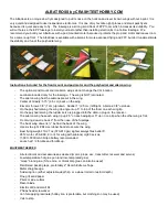
149. If the plane does not balance you can adjust the battery location or add weight to the nose or the tail of the plane until it balances
correctly.
Remember the CG is relative to the wing not the fuselage.
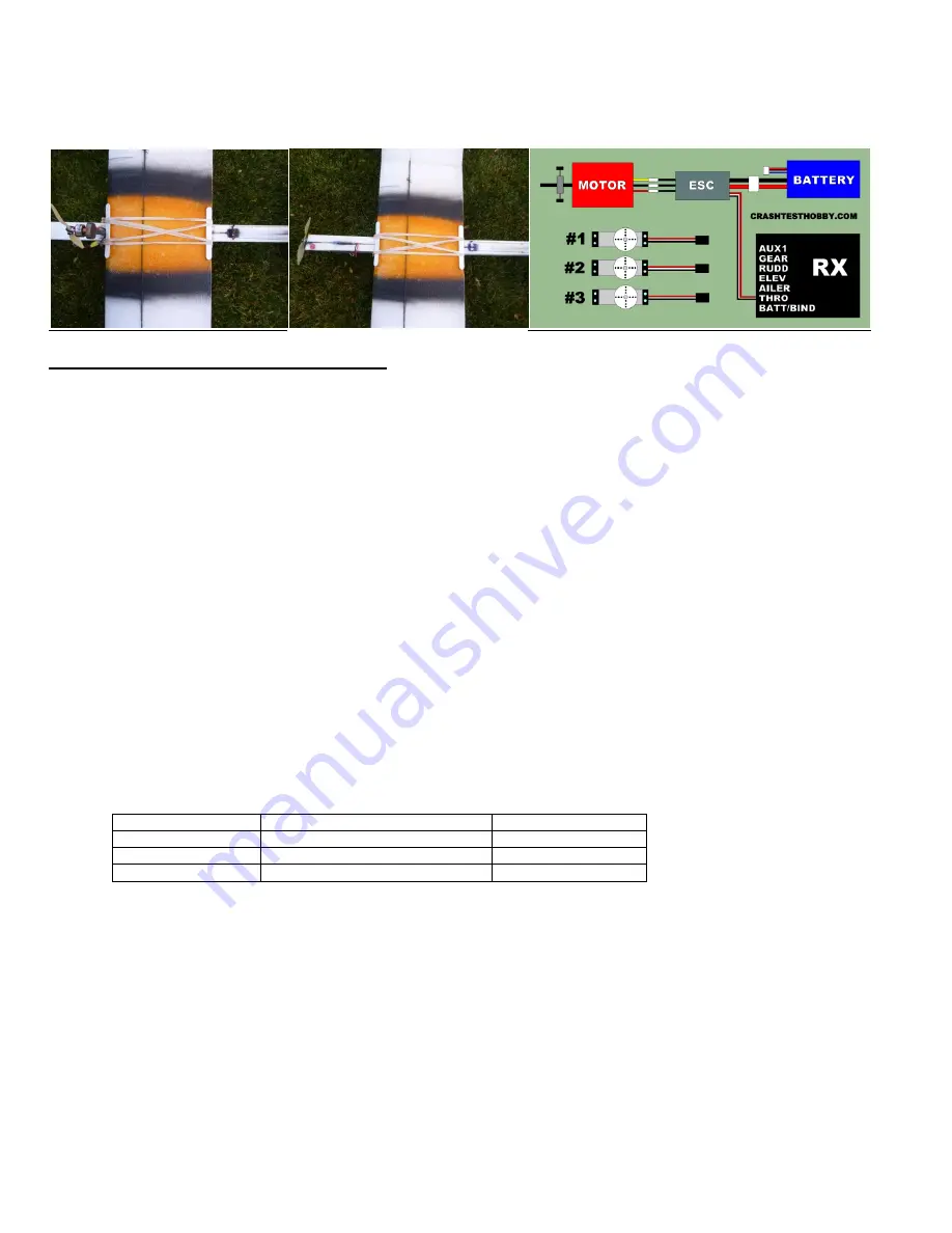
150. The wing will be held to the fuselage with 6-8 rubber bands. Not only is this an effective way to attach the two parts, but it allows for
simple takedown, travel, and storage. Attaching the wing with pod mount and front mount motors shown below.
SETTING TRIM/THROW & ELECTRONICS TESTING
151. Consult the instructions for your Transmitter and receiver (Tx/Rx) set to properly bind the two together, and then make sure the
servos and ESC are connected into the proper channels on your receiver.
152. A simple wiring diagram is above. Notice how the plugs from the motor and battery connect to the ESC and that the ESC plugs
into the Throttle plug on the receiver.
153. For the polyhedral wing, the rudder servo will plug into the aileron plug on the receiver and the elevator servo plugs into the
elevator plug on the receiver.
154. For the aileron wing, servos will plug into the aileron, elevator, and rudder plugs on the receiver.
155. Remove the servo arms from the servos. Connect all electronics, including a battery, but for safety purposes, make sure you do not
have a prop attached to your motor at this point. Turn on your transmitter, plug in your battery, and allow the servo gears to
“center” themselves.
156. Slide the push rod through the hold in the servo arm (still unattached to the servo), then slide the end of the push rod through the
guide, and into the EZ Connector on the flaps. Then re-attach the servo arm to the servo so that the arm is as close to straight up
as possible.
157. With the EZ Connectors still loose, use the Subtrim function on your transmitter to set the servo arms completely straight. This
should allow for less movement from center when trimming the wing as it flies.
158. Make sure your elevator and rudder are straight, then tighten the set screw on the EZ connectors.
159. Set the wing on a flat surface, and hold a ruler vertically behind the trailing edge of the elevator. Use your transmitter to set the
throw (range of movement) on the elevator to 3/8” (1cm) up and 3/8” down. Make sure your stick movement translates to the
proper up/down on your elevator: This can also be adjusted by putting the push rod close to the center of the servo and at the top
of the control horn.
160. Hold the ruler horizontally behind your rudder, and again use your transmitter to set the throw of the
rudder, 5/8” (2 cm) left, and
5/8” right. : This can also be adjusted by putting the push rod close to the center of the servo and at the top of the control horn.
STICK UP
Elevator down
NOSE DOWN
STICK DOWN
Elevator up
NOSE UP
STICK LEFT
Rudder left
NOSE LEFT
STICK RIGHT
Rudder right
NOSE RIGHT
161. Test the throttle and make sure the motor is turning in the correct direction. If not, unplug two of the three connectors between the
motor and the ESC and reverse them, then try again. (Be sure your prop is not attached, for safety purposes.)
162. The propeller has the writing facing forward (the direction the plane is flying). Make sure it is on frontwards and well secured.
163.
When you’re ready to fly, lay the wing on top of the fuselage, and check your center marks, front and back, to make sure the wing
is centered. Use four rubber bands (included in the kit) from dowel to dowel, to attach the wing to the fuselage. Two rubber bands
go straight, and two cross in the middle.
164.
It’s always a good idea to have someone else double check your work. Field test and range check your equipment, then launch,
trim, and enjoy!
165.
NOTE!!! Launching the Albatross is different than other planes.
The Albatross is designed to be self stabilizing so it will level
its nose and wings without flyer input but it has to be moving for this to happen. The downward angle of the motor mount mean
the
plane is much more likely to nose dive than take off until it is up to speed if it is launched with too forceful a throw, or with too much
throttle or throttle advanced too quickly. Instead, launch ½ throttle, and release the plane gently at a slightly upward angle.
Slowly
throttle up until aerodynamics take over,
and the plane gets lift. Once it is flying you won’t notice the difference in flying and you will
be amazed at how the plane can be so stable and easy to fly.


