


PN 26037-00 R072208
47
In the following section, we have listed many of the problems, causes and solutions to the problems that you may encounter.
If you encounter a problem that is difficult to solve, even after having read through this trouble shooting section, please call your local
Crary dealer. Before you call, please have this manual and the serial number from your machine ready.
TRoubleShooTing
Section
7
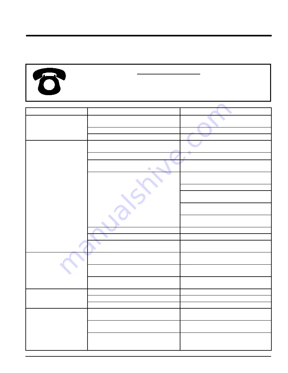
befoRe You call
please have the following information available:
Serial # ________________________ ______
pRoblem
poSSible cauSe
SoluTion
Shattering of grain ahead of cutter
bar
Reel speed not coordinated with ground speed, caus-
ing excessive agitation before crop is cut.
Adjust reel speed to coordinate with ground speed so
reel will move crop evenly.
Reel is positioned too low.
Raise reel.
Ground speed too fast for conditions of crop.
Slow ground speed.
Cut crop building up and falling
from front of cutter bar or loss of
grain heads at cutter bar.
Reel not adjusted low enough for proper delivery of
cut crop to auger.
Set reel low enough to sweep material from cutter
bar.
Insufficient ledge for crop travel.
Extend rigid cutter bar.
Auger clearance too high from platform bottom.
Adjust outer ends of auger to 1/2” (13mm) clearance
of platform bottom and check finger clearance.
Insufficient airflow or misdirection of airflow from man-
ifold to clean off cutter bar.
Adjust manifold so that air flow is directed more at
cutter bar to keep it clean.
Clean debris from rotary screen.
Check for and clear obstruction from flex hose or
manifold.
Check butterfly position and open to allow more air
flow.
Check fan rpm, adjust combine shaft speed and
check for proper gear box ratio for combine.
Reel speed too slow.
Increase speed of reel.
Reel is positioned too high.
Move reel back and then down.
Build up of grain on cutterbar.
Lower height of reel and set fore-and-aft position as
close as possible to cutter bar and auger.
Uneven or bunched feeding of crop
to cylinder.
Feeder chain carrying straw back around and disrupt-
ing crop flow to the cylinder.
Extend feederhouse stripper down to stop straw from
filtering back out.
Crop “tailing in” to the auger (heads not feeding first).
Rotate manifold so that air flow is directed higher on
the crop.
Cutter bar not at recommended speed.
Check basic speed of combine (see combine owner’s
manual).
Gear box leaking or overheating.
Incorrect oil type or level.
Check level and replace if necessary.
Breather plugged.
Remove breather, clean and reinstall.
Seals are leaking.
Install new seal kit.
Rotary screen plugs.
Debris is pinched between the base and the screen,
stopping the rotor.
Adjust air base closer to the screen.
Screen cleaner not adjusted properly.
Adjust the screen cleaner to revolve close to the
screen, but not touching it.
Needs Rotary Screen Wrap.
Contact Crary Dealer for Rotary Screen Wrap (P/N
25592-12). This wrap will prevent debris from becom-
ing lodged between the base and the rotary screen.
Содержание CWS 1010
Страница 35: ...PN 26037 00 R072208 31 ASSEMBLY Figure 27 Air hose installation 4 15 FAN HOSE ASSEMBLY...
Страница 54: ......
Страница 55: ......
Страница 56: ...237 12th St NW P O Box 849 West Fargo ND 58078 0849 PH 1 800 247 7335 FAX 701 282 9522 www crary com...


