background image

bearing (4) straight off of seal plate (2). Inspect all parts for signs
of wear and replace as needed.

CAUTION: - Handle seal parts with extreme care.
DO NOT scratch or mar lapped surfaces.

F-3.2) Replacing Bearings: 

When replacing bearings, be careful to not damage the rotor or
shaft threads. Press the old bearings off the shaft with an arbor
press or gear puller. Clean the shaft thoroughly. Apply adhesive
compound to shaft and press new bearing on, pushing only on
the inner race, until it seats against shoulder of shaft (see fig.8)

IMPORTANT: - All parts must be clean before
reassembly.

F-3.3) Reassembly:


Make sure shaft seal (3) is clean and in proper position as per
section F-4.2 before reassembling rotor and bearing. Slide
lower bearing and rotor shaft squarely into the seal plate (2)
until bearing seats on the bottom. Insert snap ring (5) into seal
plate with flat edge against outer race of bearing. Place motor
stator squarely onto seal plate and tighten motor screws.  Install
square ring squarely (11) onto seal plate. With cord assembly
(8) properly assembled, slip cord through motor housing (see
Fig. 4). Connect motor wires to cord set as per figure 5 & 6. 

Place motor housing squarely onto seal plate while pulling
excess cord through hole. Tighten socket head screws (13) into
motor housing. Tighten gland nut (8a) against washers (8b) and
grommet (8c). Refill with cooling oil as per paragraph F-1.3. 

F-4)  Shaft Seal Service

F-4.1) Dissassembly and Inspection:

Disassemble pump motor as per section F-3.1. Inspect seal for
signs of wear such as uneven wear pattern on the stationary
member or chips and scratches on either sealing face. Do not
interchange seal components. Replace entire seal if damage
occurs.

F-4.2) Replacing Shaft Seal (refer to fig. 6 & 7):

When replacing the shaft seal (3), remove used rotating
member (3c), spring (3b), and spring retainer (3a) from motor
shaft. Press used stationary member (3d) from the seal plate
(2). At reassembly, clean seal cavity thoroughly and apply a
light coat of oil. Lightly oil the rubber ring (

DO NOT

 use grease)

and press the stationary member firmly into the seal plate using
a seal pusher (See Parts List- Seal Tool Kit), nothing but pusher
to come in contact with seal face (see Fig. 7a).

Fig. 8

PUMP END

(Outboard End)

MOTOR END

(Inboard End)

BEARING (4)

SNAP RING (5)

SEAL PLATE (2)

STATIONARY (3d)

Polished Mating Surface

ROTATING MEMBER (3c)

SPRING (3b)

RETAINING RING (3a)

EXCLUSION SEAL (14)

SLEEVE (1a)

SEAL PLATE

 SEAL PUSHER

STATIONARY MEMBER (3d)

Polished  Face Out.

Fig. 7a

10

Содержание WEINMAN WE411

Страница 1: ...7 773 7157 www weinmanpumps com PUMPS SYSTEMS A Crane Co Company IMPORTANT Read all instructions in this manual before operating pump As a result of Crane Pumps Systems constant product improvement program product changes may occur As such Crane Pumps Systems reserves the right to change product without prior written notification DISCONTINUED Parts may NOT be available Manual Index ...

Страница 2: ...IEW Fig 10 15 PARTS LIST 16 17 RETURNED GOODS POLICY 19 WARRANTY START UP REPORT WARRANTY REGISTRATION SPECIAL TOOLS and EQUIPMENT INSULATION TESTER MEGGER DIELECTRIC TESTER SEAL TOOL KIT see parts list PRESSURE GAUGE KIT see parts list Other brand and product names are trademarks or registered trademarks of their respective holders Weinman is a registered trademark of Crane Pumps Systems Inc Cran...

Страница 3: ...ge openings DO NOT insert fingers in pump with power connected Always wear eye protection when working on pumps Make sure lifting handles are securely fastened each time before lifting DO NOT operate pump without safety devices in place Always replace safety devices that have been removed during service or repair Secure the pump in its operating position so it can not tip over fall or slide DO NOT...

Страница 4: ...e 300 Series Stainless CABLE ENTRY 15 ft 4 5M Cord w Plug On 115 Volt Pressure Grommet For Sealing And Strain Relief SPEED 1750 RPM Nominal UPPER BEARING Design Sleeve Lubrication Oil Load Radial LOWER BEARING Design Single Row Ball Lubrication Oil Load Radial Thrust MOTOR Design NEMA L Torque Curve Completely Oil Filled Squirrel Cage Induction Insulation Class A SINGLE PHASE Permanent Split Capac...

Страница 5: ...ginal shipping container and on initial start up rotate impeller by hand to assure seal and impeller rotate freely B 4 SERVICE CENTERS For the location of the nearest Weinman Pumps Service Center check your catalog your Weinman Pumps Inc representative or Weinman Pumps Inc Service Department in Piqua Ohio telephone 937 778 8947 SECTION C INSTALLATION C 1 Location These pumping units are self conta...

Страница 6: ...t Attach the level control to the discharge hose in the manner described above 4 Plug the level control plug into the receptacle then plug the pump into the piggyback plug One cycle of operation should be observed so that any potential problems can be corrected 5 It is recommended that the float should be set to insure that the sump well liquid level never drops below the top of the motor housing ...

Страница 7: ...e rotation is incorrect for a single phase pump contact a Weinman Pump Service Center D 2 2 Incorrect Rotation for Three Phase pumps In the event that the rotation is incorrect for a three phase installation interchange any two power cable leads at the control box DO NOT change leads in the cable housing in the motor Recheck the Kickback rotation again by momentarily applying power D 3 Identificat...

Страница 8: ... below 15KV breakdown then the pump must be carefully inspected for leaks at the shaft seal 3 cord inlet 8 square ring 11 and pipe plug 21 before refilling with oil To locate the leak perform a pressure test as per section F 1 4 After leak is repaired refill with new oil as per section F 1 3 TABLE 1 COOLING OIL Dielectric SUPPLIER GRADE BP Enerpar SE100 Conoco Pale Paraffin 22 Mobil D T E Oil Ligh...

Страница 9: ...tor housing on pump body Apply thread locking compound to each cap screw thread into body and torque to 8 ft lbs Check for free rotation of impeller F 3 Motor and Bearing Service F 3 1 Disassembly and Inspection Motor To examine or replace the motor 1 or bearings 4 remove body and impeller as per section F 2 1 Drain oil from motor housing as per section F 1 2 Remove socket head screws 13 Loosen gl...

Страница 10: ... figure 5 6 Place motor housing squarely onto seal plate while pulling excess cord through hole Tighten socket head screws 13 into motor housing Tighten gland nut 8a against washers 8b and grommet 8c Refill with cooling oil as per paragraph F 1 3 F 4 Shaft Seal Service F 4 1 Dissassembly and Inspection Disassemble pump motor as per section F 3 1 Inspect seal for signs of wear such as uneven wear p...

Страница 11: ...p of the seal Finger pressure is all that is needed to install the exclusion seal MOTOR SLEEVE BEARING RETAINING RING 3a SPRING 3b BULLET ROTATING MEMBER 3c SEAL PUSHER Fig 7b SECTION G REPLACEMENT PARTS G 1 ORDERING REPLACEMENT PARTS When ordering replacement parts ALWAYS furnish the following information 1 Pump serial number and date code Paragraph G 4 2 Pump model number Paragraph G 3 3 Pump pa...

Страница 12: ...Clean impeller cavity and inlet of any obstruction 9 Loosen union slightly to allow trappedair to escape Verify that turn off level of switch is set so that impeller cavity is always flooded Clean vent hole 10 Check rotation If power supply is three phase reverse any two of three power supply leads to ensure proper impeller rotation 11 Repair fixtures as required to eliminate leakage 12 Check pump...

Страница 13: ...Fig 9 13 ...

Страница 14: ...Fig 10 14 ...

Страница 15: ...Power Cable Assembly See TABLE 2 8a 1 Gland Nut 1 16 Stainless 051762 8b 2 Friction Ring 021531 8c 1 Grommet 051764 9 2 Connector 079318 10 1 Self Tapping Screw 8 32 x 3 8 lg Stainless 016660 11 1 Square Ring 019289 12 1 Motor Housing 093065 13 2 Socket Hd Cap Screw 1 4 20x 1 Stainless 018923 14 1 Exclusion Seal 068053 15 1 Impeller See TABLE 3 16 1 Nut 3 8 16 Stainless 018927 17 1 Gasket 068984 1...

Страница 16: ...5 FT 091563XJ 093291XJ 100 FT 091563XL 093291XL 125 FT 091563XP 093291XP 150 FT 091563XS 093291XS 175 FT 091563XV 093291XV 200 FT 091563XY 093291XY TABLE 3 IMPELLERS Item 15 WE411 WE411A WE421 Diameter Part No 5 55 069655 5 38 069655TA 5 25 069655TB 5 12 069655TC 5 00 069655TD 4 88 069655TE 4 75 069655TF 4 62 069655TG 4 50 069655TH 4 38 069655TJ 4 25 069655TK 4 12 069655TL 3 50 069655TR 16 ...

Страница 17: ...of the warranty contact your local Crane Pumps Systems Inc Distributor RETURNED GOODS RETURN OF MERCHANDISE REQUIRES A RETURNED GOODS AUTHORIZATION CONTACT YOUR LOCAL CRANE PUMPS SYSTEMS INC DISTRIBUTOR Products Returned Must Be Cleaned Sanitized Or Decontaminated As Necessary Prior To Shipment To Insure That Employees Will Not Be Exposed To Health Hazards In Handling Said Material All Applicable ...

Страница 18: ...subject to laboratory tests corrected for field performance Any additional guarantees in the nature of performance specifications must be in writing and such writing must be signed by our authorized representative Due to inaccuracies in field testing if a conflict arises between the results of field testing conducted by or for user and laboratory tests corrected for field performance the latter sh...

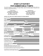
Страница 19: ...bottom Does Impeller Turn Freely By Hand YES NO Condition Of Equipment GOOD FAIR POOR Condition Of Cable Jacket GOOD FAIR POOR Resistance of Cable Jacket GOOD FAIR POOR Resistance of Cable and Pump Motor measured at pump control Red Black Ohms Red White Ohms White Black Ohms Resistance Of Ground Circuit Between Control Panel and Outside of Pump Ohms MEG Ohms Check of Insulation Red to Ground White...

Страница 20: ...n Pump Off L1 L2 L2 L3 L3 L1 Voltage supply at panel line connection Pump On L1 L2 L2 L3 L3 L1 Amperage Load connection Pump On L1 L2 L3 FINAL CHECK Is pump seated on discharge properly Check for leaks Does check valves operate properly Flow Does station appear to operate at proper rate Pump down time Noise Level High Medium Low Comments Equipment Difficulties during start up MANUALS Has operator ...

Страница 21: ...ERIAL NO PART NO BRAND FOLD HERE IMPORTANT WARRANTY REGISTRATION Your product is covered by the enclosed Warranty Complete the Warranty Registration Form and returned to Crane Pumps Systems Inc Warranty Service Group IMPORTANT If you have a claim under the provision of the warranty contact your local Crane Pumps Systems Inc Distributor ...

Страница 22: ...CRANE PUMPS SYSTEMS INC WARRANTY SERVICE GROUP 420 THIRD STREET P O BOX 603 PIQUA OHIO 45356 0603 U S A PLACE STAMP HERE FOLD HERE AND TAPE DO NOT STAPLE ...

Отзывы: