7
In the event of an overtemperature, the source of this
condition should be determined and rectified immediately.
Thermal protection shall not be used as a motor overload
device. A separate motor overload device must be
provided in accordance with NEC codes.
DO NOT
LET THE PUMP CYCLE OR RUN IF AN OVERLOAD
CONDITION OCCURS !
Thermal Protection (SGV2022L) -
The normally closed
(N/C) thermal overload is embedded and wired in series
with the motor windings. It monitors for excessive heat
and/or current draw in the event an overload condition
occurs. The thermal overload will trip when the windings
become too hot causing the pump to stop, and will
automatically reset itself when the pump motor cools
to a safe temperature. In the event of an overload, the
source of this condition should be determined and rectified
immediately. The thermal protection provided in the pump
can be used as a motor overload device. A separate
motor overload device is not required.
DO NOT LET THE
PUMP CYCLE OR RUN IF AN OVERLOAD CONDITION
OCCURS !
Moisture Sensors: (Optional) -
A normally open (N/O)
detector is installed in the pump seal chamber which will
detect any moisture present. It is recommended that this
detector be connected in series to an alarm device or
the motor starter coil to alert the operator that a moisture
detect has occurred. In the event of a moisture detect,
check the individual moisture sensor probe leads for
continuity, (∞ resistance = no moisture ) and the junction
box/control box for moisture content. This situations may
induce a false signal in the moisture detecting circuit. If
none of the above tests prove conclusive, the pump(s)
should be pulled and the source of the failure identified
and repaired.
IF A MOISTURE DETECT HAS OCCURRED SCHEDULE
MAINTENANCE AS SOON AS POSSIBLE.
Wire Size -
If additional cable is required consult a
qualified electrician for proper wire size.
Cable Connections:
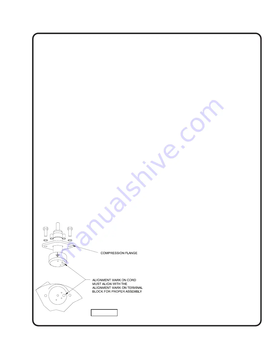
Power/Control Cable- Insert female end of cable plug into
housing bore aligning alignment mark with hole in terminal
block see Figure 2. Tighten bolts on compression flange
until flush with motor housing.
NOTES:
FIGURE 2


