7
4. During power black-outs, discontinue water
consumption to prevent sewage from backing up.
5. Prevent
infi ltration or direct fl ow of rain or run-off water
into the system to minimize pump cycling.
This will prevent overloading the treatment facility, and
will facilitate swift transportation of sewage.
6. Always keep the shut-off valve completely open when
system is in operation, (unless advised otherwise by the
proper
authorities).
7. Keep the control panel locked or confi ned to prevent
unauthorized access to it.
8. If the pump is idle for long periods of time, it is
advisable to start the pump occasionally by adding
water to the system.
9. Before removing the pump from the system, be sure
to close the shut-off valve. (This prevents backfl ow
from the pressure sewer.)
10. Make sure level controls are provided at time of
installation.
11. Recommended starts per hour, 6 to 8, no more than 10.
D-3) Start-Up Report:
Included at the end of this manual are two start-up report
sheets, these sheets are to be completed as applicable.
Return one copy to Barnes Pumps and store the second
in the control panel or with the pump manual if no control
panel is used. It is important to record this data at initial
start-up since it will be useful to refer to should servicing
the pump be required in the future.
D-3.1) Identifi cation Plate:
Record the numbers from the pump’s identifi cation plate
on both START-UP REPORTS provided at the end of the
manual for future reference.
SECTION E: SERVICE AND REPAIR
NOTE: All item numbers in ( ) refer to Figures 8 & 9.
WARNING ! - Electrical power to the pump
motors must be disconnected and locked out
to prevent any dangerous electrical hazards
or personnel danger before any service work
is done to the pump.
CAUTION ! - Operating pump builds up heat
and pressure; allow time for pump to cool
to room temperature before handling or
servicing.
E-1) Lubrication:
Anytime the pump is removed from operation, the oil in
the seal chamber (27) should be checked visually for oil
level and contamination.
E-1.1) Checking Oil:
With a fl ashlight, visually inspect the oil in the seal
chamber (27) to make sure it is clean and clear, light
amber in color and free from suspended particles.
Milky white oil indicates the presence of water. Oil must
completely fi ll the seal chamber.
E-1.2) Testing Oil:
1. Place pump on it’s side, remove pipe plug (27) on and
drain oil into a clean, dry container.
2. Check oil for contamination using an oil tester with a
range to 30 Kilovolts breakdown.
3. If oil is found to be clean and uncontaminated
(measure above 15 KV. breakdown), refi ll seal
chamber housing as per section E-1.3.
4. If oil is found to be dirty or contaminated (or measures
below 15 KV. breakdown), the the pump must be
carefully inspected for leaks at the shaft seals (5) &
(12), pipe plug (27), O-rings (11) & (20) before refi lling
with oil. To locate the leak, perform a pressure test as
per section E-1.4. After leak is repaired, refi ll with new
oil as per section E-1.3.
E-1.3) Replacing Oil:
Seal Chamber- Set unit on its side with fi ll plug (27)
downward, (located on intermediate coupling 6), remove
plug (27) and drain all oil from seal chamber. Set unit on
its side, with plug (27) upward, and refi ll completely with
(see parts list for amount) new oil as per Table 1. Apply
pipe thread compound to threads of pipe plug (27) and
assemble to intermediate coupling (6).
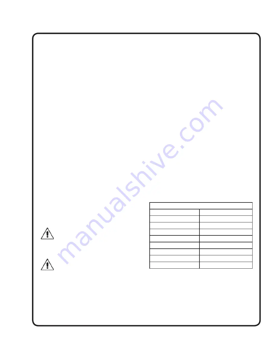
TABLE 1 - COOLING OIL - Dielectric
SUPPLIER
GRADE
BP
Enerpar SE100
Conoco
Pale Paraffi n 22
Mobile
D.T.E. Oil Light
G & G Oil
Circulating 22
Imperial Oil
Voltesso-35
Shell Canada
Transformer-10
Texaco
Diala-Oil-AX
Woco
Premium 100
E-1.4) Pressure Test:
Seal Chamber -
Remove pipe plug (27) from
Intermediate Coupling (6) and check that the seal
chamber is full of oil. Apply pipe sealant to pressure
gauge assembly and tighten into hole in Intermediate
Coupling (6).
Содержание DGV2042
Страница 12: ...12 FIGURE 8 ...
Страница 13: ...13 FIGURE 9 ...


