6
4. a. If the pump is furnished with threaded discharge
fi ttings, unscrew the pipe coupling or fl ange
(295) from the top end of the discharge pipe
then remove the top pipe nut (294) and unscrew
the lower pipe nut to the end of the threads.
Unscrew the discharge pipe (161) from the
discharge elbow (105).
b. If the pump is furnished with combination elbow
(105), remove the cap screws and nuts (267)
and (268) at the pump discharge fl ange.
5. Liquid end disassembly
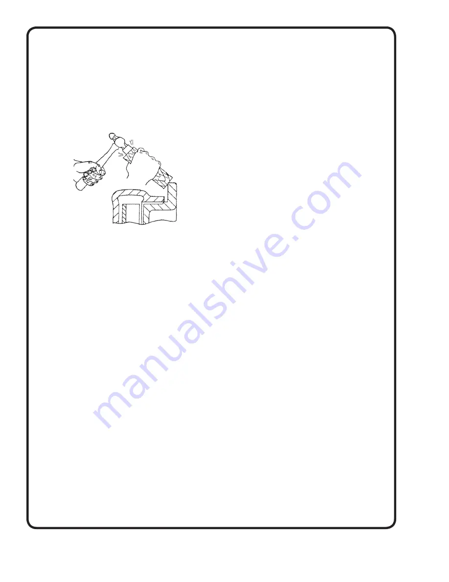
a. Remove cap screws (215), then place a block
of wood against the fi nished fl ange or back
of the suction cover (9) and tap the block lightly
with a hammer to loosen the suction cover.
Remove the suction cover and the gasket (73).
b. Bend and remove the cotter pin (269) and the
castellated impeller nut (24). Hold shaft with a
wrench at the coupling (42) and unscrew the
impeller nut (24) by turning counter clockwise,
also remove the impeller washer (270).
c.
To remove impeller (2) from the shaft (6) it will
be necessary to make 3 special jackscrews
depending upon the size of the liquid end as
follows:
1.) If the discharge outlet of the casing (1)
is threaded 1”, 1½” or 2½” and the
impeller diameter is 6” or less, the
required jackscrews are 3/8” x 16NC,
1¾”
long.
2.) For all other sizes of liquid ends the
required jackscrews are 1/2” x 13NC, 3”
long.
Thread the jackscrews into the 3 tapped holes
in the impeller shroud and tighten alternating
jackscrews, until the impeller is forced from
the shaft. Lift impeller key (32) from its seat.
d. The casing (1) and throttle housing (99) may be
removed from the column pipe (101) after
removing cap screws (212).
e. Inspect the throttle bushing (252) for excessive
wear and replace by unscrewing the cap screw
(218) and pressing the bushing from the
housing. Press new bushing into the throttle
housing (99), aligning the slot with the cap screw
(218) then tighten cap screw until fi rm. Slide
defl ector (40) from the shaft.
L - TO INSPECT BALL BEARINGS &
SEALS OR SHAFT
1. Remove Liquid end assembly.
2. Remove coupling (42) and key (46) from shaft (6).
3. Remove cap screws (221) and nuts (261) and lift
driver pedestal (81) from frame (19).
4. Remove cap screw (213). Unscrew the 3 lock nuts
(204) until against the head of the jackscrew (286)
then remove jackscrews. Slide bearing cover (37)
with seal (49) off the top end of the shaft (6). Inspect
the seal and replace if worn.
5. Bend tape on bearing lock washer (69) then unscrew
and remove the bearing lock nut (22) and bearing
lock washer (69).
6. Replace the jackscrews (286) in the bearing housing
fl ange and toghten the jackscrews to raise the
bearing housing (33) and ball bearing (18) from the
top of the frame (19). A pry bar may be required to
assist in removing the bearing housing. Carefully
press the ball bearing from the bearing housing.
7. Carefully withdraw the pump shaft and ball bearing
(16) upward through the frame (19). Remove the
bearing (16) from the shaft.
8. Inspect the bearing cover seal (47) and if worn
replace with new seal. Bearing cover (35) and seal
may be removed from the frame using a piece of
pipe or tubing inserted through the top of the frame
to force the bearing cover from the frame.
M - TO REASSEMBLE BALL
BEARINGS AND SEALS
1. Slide bearing (16) onto the shaft. Position the
bearing so that the inner bearing race is against the
shaft
shoulder.
CAUTION:
Apply force only to the
inner bearing race.
2. If the bearing cover (35) and the seal (47) were
removed from the frame, apply suffi cient grease to
fi ll the space below the ball bearing (16). Press
bearing cover with seal into the frame from the
impeller end until the bearing cover is fl ushed with
the frame. Be sure that seal (47) is installed with the
spring side of the seal toward the impeller.
Содержание DEMING 5460 Series
Страница 12: ...Notes ...


