8
ASSEMBLY
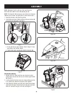
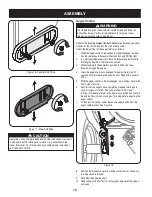
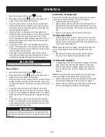
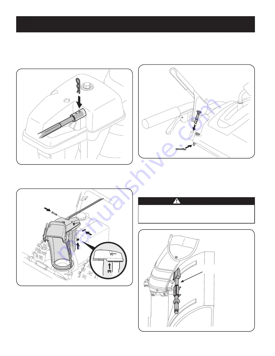
8. Secure the round end of the chute control rod to the chute control
assembly with the cotter pin removed earlier. See Figure 10.
NOTE:
The second hole is used to achieve further engagement of the
chute control rod into the pinion gear if required, refer to “Chute Control
Rod” in the “Adjustment” section.
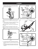
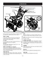
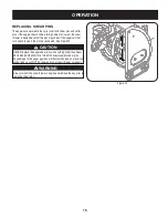
8. Finish securing chute rotation assembly to chute support bracket with
wing nut, clevis pin and cotter pin removed earlier. See Figure 11.
NOTE:
An extension cord may be fastened with a cable tie to the
rear of the auger housing for shipping purposes. Cut the cable tie and
remove it before operating the snow thrower.
CAUTION: Prior to operating your snow thrower, refer to Auger
Control Test in the “Operating” section. Read and follow all
instructions carefully, and perform all adjustments to verify your
snow thrower is operating safely and properly.
Shear Pin Storage (optional)
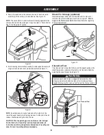
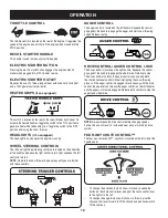
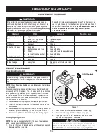
Replacement auger shear pins are included with this manual, or
stowed in the plastic handle panel as shown in Figure 12.
Refer to
Augers in the Maintainance Section for more
information regarding
shear pin replacement.
Clean-Out Tool
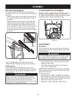
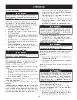
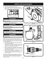
The clean-out tool is mounted to the rear of the auger housing with a
mounting clip and a cable tie at the factory. Cut the cable tie before
operating the snow thrower. See Figure 13.
Figure 10
Figure 11
Figure 12
Figure 13
Chute Clean-out Tool
WARNING
Never use your hands to clear a clogged chute assembly. Shut
off engine and remain behind handles until all moving parts have
stopped before using the clean-out tool to clear the chute assembly.


