background image

INSTALLATION
MANUAL

CAUTION:

READ ALL SAFETY GUIDES BEFORE YOU 
START TO INSTALL UNIT.

SAVE THIS MANUAL

SPLIT-SYSTEM

AIR COOLED

EVAPORATOR BLOWER

MODELS: LL-15, LL-20


66339-BIM-C-0206

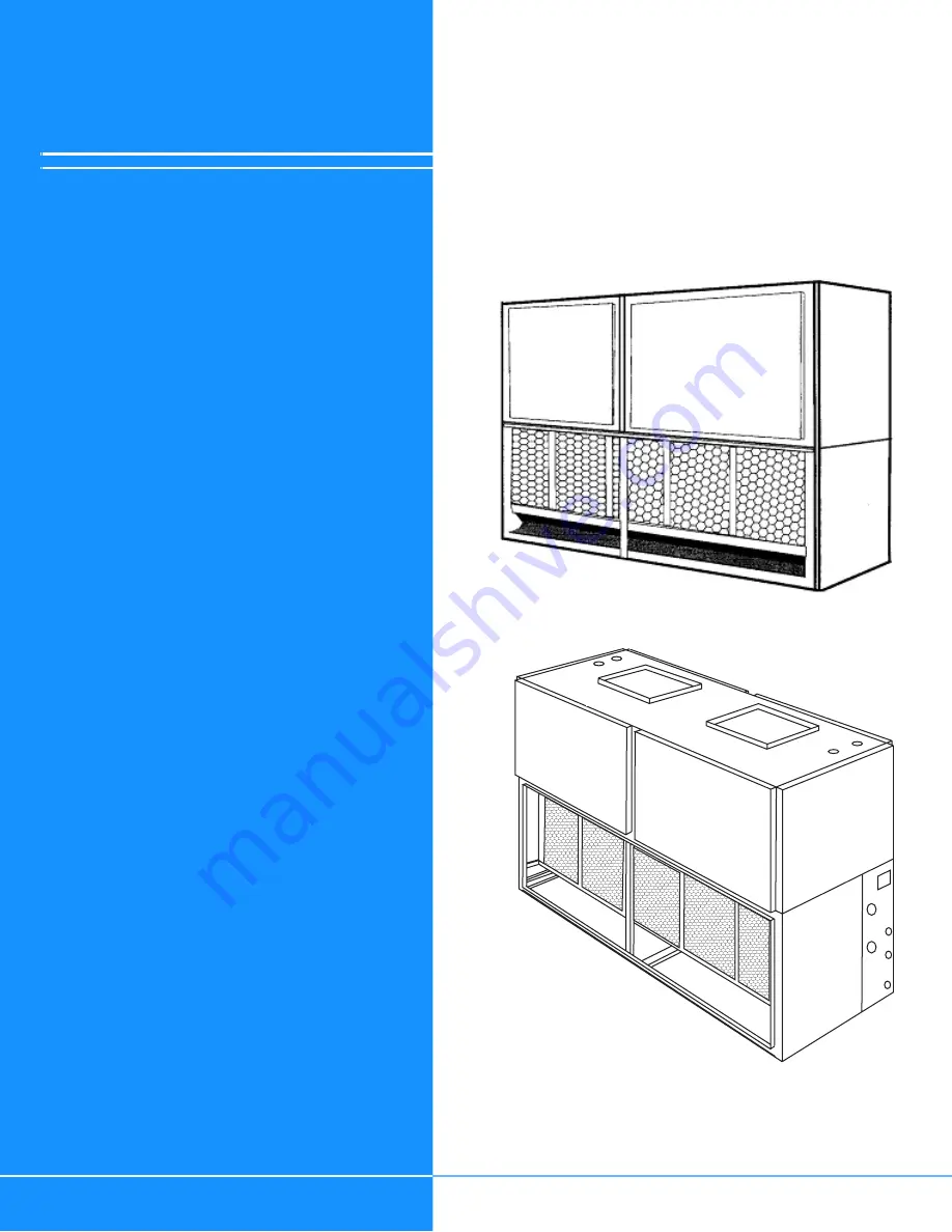
LL-20

LL-15

CONTENTS

NOMENCLATURE . . . . . . . . . . . . . . . . . . . . . . . . . . . . . .3

GENERAL  . . . . . . . . . . . . . . . . . . . . . . . . . . . . . . . . . . . .4

NOTES, CAUTIONS AND WARNINGS. . . . . . . . . . . . . .4

REPLACEMENT PARTS . . . . . . . . . . . . . . . . . . . . . . . . .4

INSPECTION . . . . . . . . . . . . . . . . . . . . . . . . . . . . . . . . . .4

LIMITATIONS. . . . . . . . . . . . . . . . . . . . . . . . . . . . . . . . . .5

INSTALLATION . . . . . . . . . . . . . . . . . . . . . . . . . . . . . . . .9

FOR A COMPLETE TABLE OF CONTENTS, SEE FOLLOWING 
PAGE.

Содержание LL-15

Страница 1: ...SAVE THIS MANUAL SPLIT SYSTEM AIR COOLED EVAPORATOR BLOWER MODELS LL 15 LL 20 66339 BIM C 0206 LL 20 LL 15 CONTENTS NOMENCLATURE 3 GENERAL 4 NOTES CAUTIONS AND WARNINGS 4 REPLACEMENT PARTS 4 INSPECTIO...

Страница 2: ...DUCT ANGLES 11 DRAIN CONNECTIONS 11 REFRIGERANT MAINS 11 EVAPORATOR SECTION PIPING 12 SUPPLY AIR BLOWER ADJUSTMENT 12 ELECTRICAL CONNECTIONS 14 INDOOR UNIT ELECTRICAL RATINGS 14 LIST OF FIGURES Fig P...

Страница 3: ...ump F Product Identifier F R 22 Standard Efficiency 2 Pipe L R 22 Standard Efficiency 4 Pipe 15 Nominal Cooling Capacity MBH 15 15 Ton 20 20 Ton C Heat Type C Cooling Only 00 Nominal Heating Capacity...

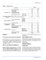
Страница 4: ...9675 Toll Free Fax 877 379 7920 INSPECTION As soon as a unit is received it should be inspected for possible damage during transit If damage is evident the extent of the damage should be noted on the...

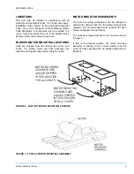
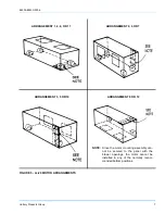
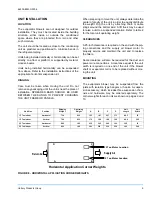
Страница 5: ...ages are ordered and shipped separately for field mounting MOTOR MOUNT ARRANGEMENTS The motor mounting arrangement can be changed to allow motor access based on the airflow arrangement required The re...

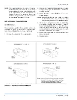
Страница 6: ...nels from the blower section 2 Remove the Phillips machine screws located inside casing corner angles that hold the coil and blower sections together 3 Rotate the blower section for the desired air di...

Страница 7: ...ENTS ARRANGEMENT 1 4 8 OR 11 ARRANGEMENT 3 5 OR 10 ARRANGEMENT 2 6 OR 7 NOTE Since the motor mounting assembly can not be secured to the panel with the blower openings the motor cannot be installed in...

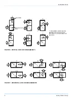
Страница 8: ...MENTS AIR AIR BLOWER 1 EVAPORATOR COIL AIR AIR 2 AIR AIR AIR AI R 4 AIR AIR 5 AIR AIR 6 3 IF REQUIRED SOME AIR CAN BE BROUGHT THROUGH THE BOTTOM OF THE EVAPORATOR SECTION FIGURE 7 HORIZONTAL AIRFLOW A...

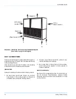
Страница 9: ...round the bottom skid A lift truck may be used to raise a unit to a suspended location Refer to table 2 for the total unit operating weight CLEARANCES A 25 inch clearance is required on the end with t...

Страница 10: ...the cooling season or through an unheated space during the heating season 2 Include a vapor barrier around the outside to pre vent the absorption of moisture 3 Be no less than 2 inches thick with the...

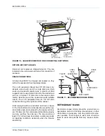
Страница 11: ...e of the cabinet Drain piping should be constructed as shown in figure 9 The 5 inch dimension is intended to exceed the neg ative static pressure developed by the supply air blow ers If it does not th...

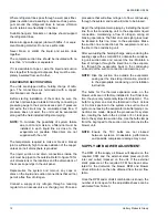
Страница 12: ...o an access valve or charging tail Choose a procedure that will allow nitrogen to flow continuously through the system and reach all joints to be brazed Begin the refrigerant main piping by installing...

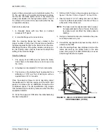
Страница 13: ...applied force of 2 to 3 pounds Once the supply air blower motor is operating adjust the resistances in both the supply and the return duct system to balance the air distribution throughout the conditi...

Страница 14: ...13 HOLE LOCATIONS FOR PRESSURE DROP READINGS 20 TON Approximate RPM Chart Turns Open LL 15 LL 20 Low Static Drive Kit Hi Static Drive Kit Low Static Drive Kit Hi Static Drive Kit 5 650 840 580 700 4 6...

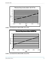
Страница 15: ...ON Pressure Drop Across Indoor Coil 15 Ton 0 0 05 0 1 0 15 0 2 0 25 0 3 0 35 0 4 0 45 0 5 4000 5000 6000 7000 8000 CFM I W C FIGURE 15 PRESSURE DROP ACROSS INDOOR COIL 20 TON Pressure Drop Across Indo...

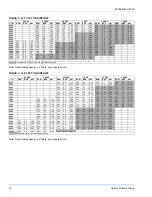
Страница 16: ...8 7600 719 2 8 2 61 792 3 3 3 12 877 4 0 3 7 956 4 6 4 31 7800 730 3 0 2 78 807 3 5 3 31 888 4 1 3 88 960 4 8 4 49 Denotes use of 5 hp motor with high static pulley kit TABLE 4 LL 20 20 TON AIRFLOW 0...

Страница 17: ...BLOWER PERFORMANCE 15 TON BLOWER PERFORMANCE 0 4 0 6 0 8 1 1 2 1 4 1 6 4200 4700 5200 5700 6200 6700 7200 7700 CFM ESP FIGURE 17 20 TON BLOWER PERFORMANCE 20 TON BLOWER PERFORMANCE 0 4 0 6 0 8 1 1 2 1...

Страница 18: ...MENSIONS LL 15 and LL 20 TABLE 5 UNIT DIMENSIONS LL 15 AND LL 20 MODEL A B C D E F G H J K L M LL 15 89 1 2 85 0 26 0 29 1 2 59 1 7 16 15 7 8 12 7 16 15 13 16 16 16 20 3 4 LL 20 100 1 8 95 5 8 33 1 4...

Страница 19: ...66339 BIM C 0206 Unitary Products Group 19 FIGURE 19 PIPING and ELECTRICAL CONNECTION LOCATIONS...

Страница 20: ...e without notice Printed in U S A 66339 BIM C 0206 Copyright 2006 by Unitary Products Group All rights reserved Supersedes 66339 BIM B 0304 035 18503 001 B 0304 Unitary 5005 Norman Products York OK Gr...

Отзывы: