background image


B

LOWER 

R

EPAIR 

&


M

AINTENANCE 

M

ANUAL 

F

OR 

C

HROME 

B

LOWERS


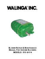
MODELS: 510 & 614 


Содержание 510

Страница 1: ...BLOWER REPAIR MAINTENANCE MANUAL FOR CHROME BLOWERS MODELS 510 614...

Страница 2: ...Blower Repair Maintenance Manual 34 05198 6 v1 2 11 2014 2...

Страница 3: ...waving walinga com ORIGINAL PARTS SALES For Customers in Canada Jack Lodder ext 224 jel walinga com arts Department Fax 519 824 0367 For Customers in USA John VanMiddlekoop 800 466 1197 ext 3 jvm wali...

Страница 4: ...aintain and service your WALINGA blower follow the instructions carefully and you will be rewarded with long life service TABLE OF CONTENTS Special Features Of Walinga Blowers 7 Section One Lubricatio...

Страница 5: ...the user the most compact unit possible The drive shaft is extended for direct coupling or to accommodate a multiple V belt drive The following standard blowers are available from Walinga WALINGA 510...

Страница 6: ...e to suit specific applications Walinga or a trained dealer must be consulted prior to installation or perform this conversion to ensure that the warranty coverage is not voided Note that direction of...

Страница 7: ...iginal factory clearances Bearings are protected from dirt and contamination by oil seals Precision steel helical gears are oil lubricated by a completely self contained splash system which atomizes t...

Страница 8: ...ing loaded type Figure 5 Both valves are supplied as standard equipment Fig 6 TIMING GEARS Walinga units are fitted with precision steel helical gears and the exclusive WALINGA TIMING HUB which enable...

Страница 9: ...Blower Oil Walinga Part 98 13813 5 In most cases operating temperature of the blower will be in the 100 250 Deg F range Normally the gear case should be drained flushed and refilled every 100 hours o...

Страница 10: ...king or pounding during operation GEAR CASE REMOVAL The Gear case is secured to the headplate with socket head cap screws Figure 9 Drain oil from gear case and remove bolts Lift gear case away from he...

Страница 11: ...viewed from the drive end of the blower always face the drive shaft end when determining clearance Table 2 CLEARANCES FOR IMPELLERS INCHES GUELPH SERIES TIMING CLEARANCE TIP CLEARANCE END CLEARANCE S...

Страница 12: ...ings is to the appropriate side and the clearance measurement is truly a minimum clearance measurement Once again this minimum spec should be taken at the tightest point This means that when the shims...

Страница 13: ...e four cap screws A to locknut B and the lock washer C in one gear only Wedge the two impellers together against the exact amount of shim stock required to establish proper clearances as calculated in...

Страница 14: ...screws B Remove locknuts C lockwashers D from shaft on gear end of blower Remove bolts E and washers F from timing gears match the timing gears and lift them off of the hubs G To remove timing hubs a...

Страница 15: ...510G on the right had side and up Install the headplate on the end facing If sameheadplate is used install 2 5 16 dowel pins and two 3 8 X 1 socket cap screws in counter sunk holes also 4 3 8 X 1 soc...

Страница 16: ...step 13 and 14 If new headplates or new housing are used adjust the headplates by tabbing them from side to side and up and down until centered in housing with not less than 077 clearance Tighten the...

Страница 17: ...ing sure that the lines line up and bolt them on with 3 8 X 1 1 4 socket head capscrews and timing washers Hold the impellers together with 0 010 feeler gauge in between while installing the bolts Rot...

Страница 18: ...rom their respective serrated shafts simultaneously On completion of maintenance work the return of the gear hub sub assemblies to their matched marked positions will eliminate the need for retiming 4...

Страница 19: ...indicated and tighten against the headplate applying equal turns to each bolt to assure an even withdrawal of the cartridge Detach the cartridge and remove the bearing retaining ring from the face of...

Страница 20: ...on some units four socket head cap screws may be seen on the exposed end of the headplate D Do not remove these screws 2 Remove the button head cap screw E and the retainer plate F from the impeller...

Страница 21: ...r box cover and replace the retaining ring 5 Replace the key on the impeller shaft and press or drive with a lead hammer the pinion gear onto the shaft until it is seated against the spacer 6 Drive th...

Страница 22: ...510 13 1 53 04617 6 Serial Plate 510 Blower 14 2 58 19689 6 Adapter Plug 12MB 15 2 58 19696 6 Plug 12MB W Sight window 16 8 58 80675 6 Plug 6MB W Magnet 17 2 94 00139 6 Locknut N 06 18 2 94 00140 6 Lo...

Страница 23: ...Blower Repair Maintenance Manual 34 05198 6 v1 2 11 2014 23...

Страница 24: ...unting or pipe strains Excessive pressure differential Worn timing gears caused by improper lubrication or overloading Retime Check mounting alignment and relieve pipe strains Check manufacturer s rec...

Страница 25: ...il level dirty oil check for obstructions in the oil lines and strainer in force feed units Excessive gear wear Oil too light Use recommended weight of oil Lack of oil pressure on the force feed units...

Страница 26: ...ittle oil will ruin bearings and gears Too much oil will cause overheating and can ruin gears and cause other damage 4 Turn the unit over by hand to be certain it does not bind 5 Jog the unit with the...

Страница 27: ...supplied ii Belts are loose and remain loose until instruction 10 7 Place bearing support plate F and check the hole alignment for the mounting bolts It is important that these bolts fit freely If no...

Страница 28: ...y Cres Fergus Ontario Canada N1M 2W7 Tel 519 787 8227 Fax 519 787 8210 DISTRIBUTION AND SERVICE CENTRES 5656 Highway 6N Guelph Ontario Canada N1H 6J2 Tel 888 925 4642 FAX 519 824 5651 1190 Electric Av...

Отзывы: