7
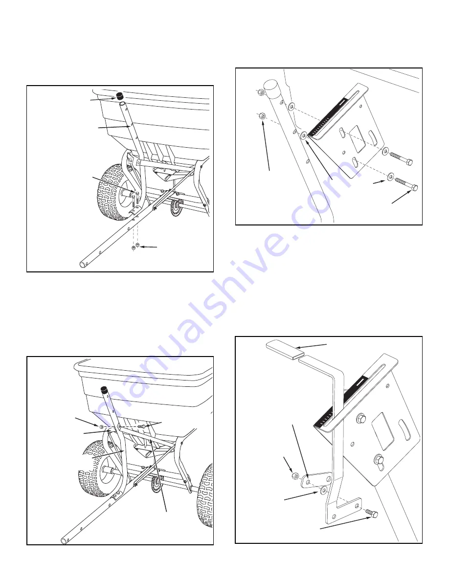
• Turn the spreader upright on its wheels.
• Assemble the flow control mounting tube to the hitch
tube using two 5/16" x 1-3/4" hex bolts and 5/16"
nylock hex nuts.
DO NOT TIGHTEN YET.
See figure 5.
• Assemble the vinyl cap onto the flow control mounting
tube. See figure 5.
FIGURE 5
FIGURE 6
• Assemble the two
INNER
hitch braces to the flow
control mounting tube using a 1/4" x 1-3/4" hex bolt
and a 1/4" nylock hex nut.
DO NOT TIGHTEN YET
.
See figure 6.
•
TIGHTEN
all nuts and bolts assembled up to this
point.
Do not collapse the tubes when tightening.
1/4" x 1-3/4"
HEX BOLT
1/4" NYLOCK
HEX NUT
HITCH BRACE
INNER
FLOW CONTROL
MOUNTING TUBE
HITCH BRACE
INNER
5/16" x 1-3/4"
HEX BOLT
5/16" NYLOCK
HEX NUT
VINYL CAP
FLOW CONTROL
MOUNTING TUBE
FIGURE 8
• Assemble the vinyl grip onto the flow control arm. See
figure 8.
• Insert the flow control arm down through the slot in
the flow control bracket. Assemble the small hole of
the flow control link to the flow control arm using a
1/4" x 1" hex bolt, a nylon washer and a 1/4" nylock
hex nut as shown in figure 8.
Tighten carefully.
The
flow control link should be snug but should pivot with
no more than slight resistance.
• Assemble the flow control mounting bracket to the
flow control mounting tube using two 5/16" x 1-3/4"
hex bolts, four 5/16" flat washers and two 5/16" nylock
hex nuts.
DO NOT TIGHTEN YET.
See figure 7.
FIGURE 7
5/16" NYLOCK
HEX NUT
5/16" x 1-3/4"
HEX BOLT
5/16" FLAT
WASHER
OFF
ON
1
2
3
4
6
7
8
9
10
5
1/4" x 1"
HEX BOLT
1/4" NYLOCK
HEX NUT
OFF
ON
1
2
3
4
6
7
8
9
10
5
FLOW
CONTROL
LINK
(small hole)
NYLON
WASHER
VINYL GRIP


