


23
SERVICE AND MAINTENANCE
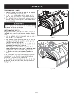
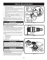
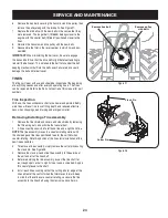
Remove the hex bolts securing the transmission drive pulley, then
6.
remove the pulley along with the two belts. See Figure 27.
Replace the old belts with the new belts in the same order they
7.
were removed. The longer belt (1916658) belongs closer to the
engine, with the shorter belt (1916657) positioned closer to the
tines.
Reinstall the transmission drive pulley with the new belts.
8.
Reassemble the tiller in the reverse order in which it was disas-
9.
sembled.
IMPORTANT
: When reinstalling the belt cover, be sure to engage
the bail and hold it so that the drive belt is tight before attempting to
reinstall the belt cover. This will enable the belt to fall under the belt
keeping mechanism built into the belt cover. Failure to do so could
damage the belt and/or belt cover.
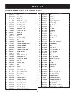
TINES
The tines will wear with use and should be inspected at the beginning
of each tilling season and after every 30 operating hours. The tines
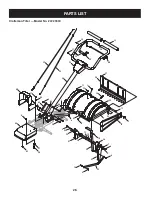
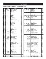
can be replaced. Refer to the Parts List section of this manual for part
numbers.
Tine Inspection
With use, the tines will become shorter, narrower and pointed. Badly
worn tines will result in a loss of tilling depth, and reduced effective-
ness when chopping up and turning under organic matter.
Removing/Installing a Tine Assembly
Remove the tine shield end covers and side shields by removing
1.
the three wing nuts on each side that secure them.
A tine assembly consists of a left hand tine and a right hand tine.
2.
NOTE
: The tine assembly moves in a counter-rotating motion with
the sharp edges of the tines positioned to enter the soil first when
counter-rotating. Note this position of the tines for reinstallation of the
new tine assemblies.
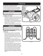
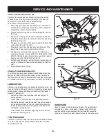
To remove a tine assembly, simply remove the cotter pin securing
3.
the clevis pin. See Figure 28.
Remove the clevis pin and slide the assembly to the outside of
4.
the unit and off of the tine shaft.
Before reinstalling the tine assembly, inspect the tine shaft for
5.
rust, rough spots or burrs. Lightly file or sand, as needed. Apply a
thin coat of grease to the shaft.
Install each tine assembly so that the cutting (sharp) edge of the
6.
tines will enter the soil first when the tiller moves forward. Keep
in mind that these tines are counter-rotating, so secure the tine
assembly to the tine shaft using the clevis pin and cotter pin.
Figure 27
Figure 28
Remove hex bolt
Remove pulley
with belts
Cotter Pin
Clevis Pin


