background image


18

BLADE GUARD 


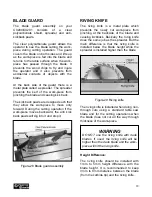
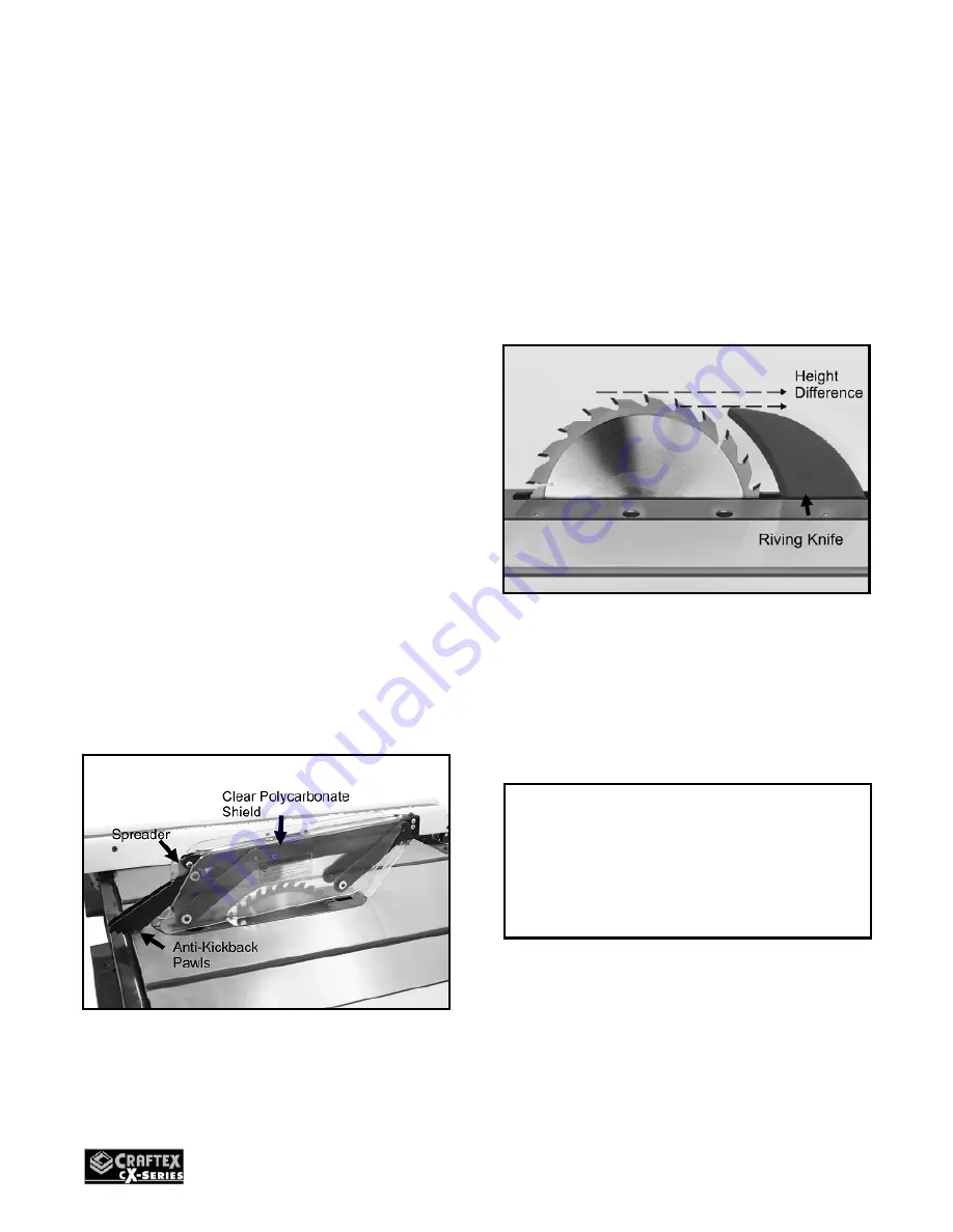
The blade guard assembly on your 
CX200/CX201 consists of a clear 
polycarbonate shield, spreader and anti-
kickback pawls. 
 
The clear polycarbonate guard allows the 
operator to see the blade cutting the work-
piece during cutting operation. The guard 
covers the blade on both sides and lifts up 
as the work-piece is fed into the blade and 
returns to the table surface when the work-
piece has passed through the blade. It 
prevents the wood chips to fly and injure 
the operator and it also prevents from 
accidental contacts of objects with the 
blade.    
 
At the back side of the guard there is a 
metal plate called a spreader. The spreader 
prevents the kerf of the work-piece from 
pinching the blade and causing kick back.  
 
The kick back pawls are designed such that 
they allow the work-piece to move only 
forward. During the cutting operation if the 
work-piece moves backward, the anti kick 
back pawls will dig into it and stop it. 


Figure-28 Blade guard assembly 


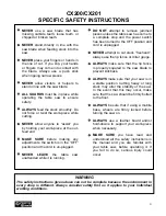
RIVING KNIFE 


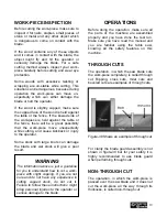
The riving knife is a metal plate which 
prevents the newly cut work-piece from 
pinching at the backside of the blade and 
causing kickback. Basically the riving knife 
does the same job as the spreader. But the 
main difference is that the riving knife is 
installed below the blade height while the 
spreader is installed higher than the blade. 


Figure-29 Riving knife 

 
The riving knife is installed when doing non-
through cuts using a standard table saw 
blade and for the cutting operations when 
the blade does not cut all the way through 
thickness of the work-piece. 


Height Difference: 


The riving knife should be installed with 
1mm to 5mm height difference with the 
blade height. It is recommended to keep 
3mm to 8mm distance between the blade 
(from the carbide tip) and the riving knife. 


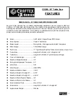
WARNING 

DO NOT use the riving knife with dado 
blades. If used, the riving knife will be 
higher than the dado blade and the work-
piece will hit the riving knife.  

Содержание CX series

Страница 1: ...CX200 10 CX201 10 HEAVY DUTY TABLE SAW WITH RIVING KNIFE User Manual ...

Страница 2: ...e 15 Fence Scale 15 Blade Guard Installation 16 Connecting to a Dust Collector 16 Basic Controls 17 Test Run 17 Blade Guard 18 Riving Knife 18 Work Piece Inspection 19 Operations 19 Through Cuts 19 Non Through Cuts 19 Ripping 20 Crosscutting 20 Miter Cuts 21 Bevel Cuts 21 Adjustments 22 Main Table to Blade Parallelism 22 Blade Guard Spreader Riving Knife Alignment 22 Tensioning the V belt 23 Repla...

Страница 3: ...LERT DO NOT use prescription or other drugs that may affect your ability or judgment to safely use your machine DISCONNECT the power source when changing drill bits hollow chisels router bits shaper heads blades knives or making other adjustments or repairs NEVER leave a tool unattended while it is in operation NEVER reach over the table when the tool is in operation ALWAYS keep blades knives and ...

Страница 4: ...o a complete stop and the power switch has been turned to the OFF position and cord is unplugged NEVER attempt to cut stock freehand always use the rip fence or miter gauge ALWAYS make sure that the rip fence is properly squared to the saw blade to prevent kickback ALWAYS make sure that your saw is in a stable position Cutting heavy or long stock may alter the stability of the saw In the event tha...

Страница 5: ...Motor Drive System Triple V Belt Drive Blade Guard Riving Knife CSA Approved UL897 Compliant Miter Gauge T Slot Miter Gauge Rip Fence T Type Heavy Duty Rip Fence Cam Lever w Optical Cursor Fence Size Length 48 x Width 4 1 8 x Height 2 1 2 Table Size Length 40 x Width 27 with Extension Wings Floor to Table Height 34 Maximum Blade Diameter 10 Riving Knife Spreader Thickness 0 1 Arbor Size 5 8 Arbor ...

Страница 6: ...8 Amp Single Phase TEFC Motor Drive System Triple V Belt Drive Blade Guard Riving Knife CSA Approved UL897 Compliant Miter Gauge T Slot Miter Gauge Rip Fence T Type Heavy Duty Rip Fence Cam Lever w Optical Cursor Fence Size Length 48 x Width 4 1 8 x Height 2 1 2 Table Size Length 73 3 4 x Width 27 with Extension Wings Floor to Table Height 34 Maximum Blade Diameter 10 Riving Knife Spreader Thickne...

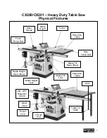
Страница 7: ...Blade Guard Fence Motor Cover Miter Gauge Blade Tilt Hand Wheel ON OFF Magnetic Switch Blade Height Hand Wheel Blade Tilt Lock Front Fence Rail Rear Fence Rail 4 Dust Port Extension Table Table Tilt Scale Legs Power Cord Extension Table Blade Height Lock ...

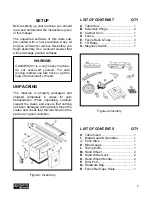
Страница 8: ...t nothing has been damaged during transit Open the crates and check that the machine and the parts are in good condition Figure 1 Inverntory LIST OF CONTENST QTY A Table Saw 1 B Extension Wings 2 C Cabinet Door 1 D Fence 1 E Fence Rails Tube 3 F 10 Blade 1 G Magnetic Switch 1 Figure 2 Inventory LIST OF CONTENTS QTY H Table Insert 1 I Blade Guard Spreader 1 J Push Stick 1 K Miter Gauge 1 L Riving K...

Страница 9: ...ady installed on the machine Some of the parts come assembled with the machine because of shipping purposes When setting up your machine you will want to find an ideal spot where your table saw will most likely be positioned most of the time Consider your complete work environment as well as working comfortability with the table saw before placing your machine in the ideal spot Figure 4 Minimum wo...

Страница 10: ...nded not to use extension cords with your CX200 CX201 Always try to position your machine close to the power source so that you do not need to use extension cords Incase if you really find it necessary to use an extension cord make sure the extension cord does not exceed 50 feet in length and the cord is 14 gauge to prevent motor damage Your CX200 CX201 should be wired with a plug having 3 prongs ...

Страница 11: ...ing the door pins into the hinge sockets on the cabinet See figure 7 Figure 7 Installing the cabinet door Install the blade tilt hand wheel onto the hand wheel shaft and secure it using set screw provided See figure 8 Figure 8 Securing the blade tilt hand wheel Now thread the hand wheel lock into the center of the hand wheel and tighten it Thread the hand wheel handle onto the hand wheel and tight...

Страница 12: ...le Secure it using cap screws and washers provided See figure 11 Figure 11 Installing the extension wings Place a straight edge on the main table and the extension wing and make sure they are flat with each other If the mating surface of the extension wing tilts down use a masking tape along the bottom edge of the main table to shim the extension wing up Figure 12 Using masking tape to shim the ex...

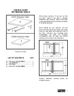
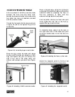
Страница 13: ...ble and secure it using hex bolts and washers provided See figure 16 Make sure the top edge of the rear rail is flush with the bottom part of the T slots on the table Figure 16 Installing rear fence rail CX200 EXTENSION TABLE Install the extension table between the front and rear fence rails securing it to the rails using hex nuts hex bolts and washers provided Figure 17 Installing the extension t...

Страница 14: ...sing cap screws and washers provided See figure 19 Figure 19 Installing CX201 extension table Place a straight edge across the extension wings and the extension table and level the extension table by adjusting the feet so that the extension is flush with the extension wings and the main table Once the table surfaces are flush with each other tighten the hex nuts on the feet up against the leg to l...

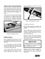
Страница 15: ... the pointer window while cutting operation If the machine comes with the pointer window mounted to the left side of the fence simply loosen the screws on the pointer window and re install it on the right side of the fence Figure 23 Installing pointer window To Install the Fence Scale Slide the fence against the saw blade and push the fence handle down to lock it on the rails Place the tape scale ...

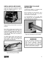
Страница 16: ...h enough to allow the work piece fed easily while cutting operation Figure 25 Blade guard installed CONNECTING TO A DUST COLLECTOR CX200 CX201 features a 4 diameter dust port to connect to a dust collector When connecting to a dust collector use a proper sized hose and make sure all the connections are sealed tightly It is recommended to use a proper sized dust collector with the CX200 CX201 to en...

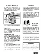
Страница 17: ...n the hand wheel When the blade is at the desired angle tighten the lock TEST RUN Once you have assembled your machine completely it is then time for a test run to make sure that the machine works properly and is ready for operation During the test run if there is any unusual noise coming from the machine or the machine vibrates excessively stop the machine immediately and disconnect from the powe...

Страница 18: ... piece moves backward the anti kick back pawls will dig into it and stop it Figure 28 Blade guard assembly RIVING KNIFE The riving knife is a metal plate which prevents the newly cut work piece from pinching at the backside of the blade and causing kickback Basically the riving knife does the same job as the spreader But the main difference is that the riving knife is installed below the blade hei...

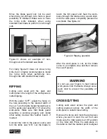
Страница 19: ...ock with large knots can damage the blade and wet stock will give a poor result OPERATIONS Before doing the operation make sure all the parts of the machine are assembled properly and you have done the test run Make sure you have read the manual and you are familiar using the table saw knowing all the safety features on this machine THROUGH CUTS The operation in which the saw blade cuts the work p...

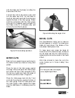
Страница 20: ...that blade guard assembly is working properly and install other safety devices like feather board if needed Connect the cord to the power source and turn the table saw ON Let the blade to reach the full speed and feed the work piece through the blade using a push stick until the work piece completely passes the saw blade See figure 32 Figure 32 Ripping operation After the work piece is cut let the...

Страница 21: ...ece Use the bar as a guide and mark the angle of cut with a pencil as shown in figure 34 Place the miter gauge back into the T slot and hold the work piece against the face of the miter gauge Push the work piece with the miter gauge slowly against the blade until the work piece is completely past the blade Figure 34 Marking the angle of cut BEVEL CUTS The CX200 CX201 blade can be tilted to the lef...

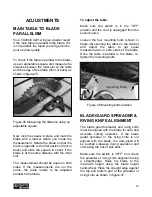
Страница 22: ...ds to be adjusted parallel to the blade To adjust the table Make sure the switch is in the OFF position and the cord is unplugged from the power source Loosen the four mounting bolts shown in figure 36 securing the table on the cabinet and adjust the table to get equal measurements on both sides of the blade Once the table is parallel to the blade re tighten the mounting bolts Figure 36 Mounting b...

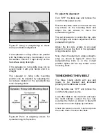
Страница 23: ...the mounting block and adjust the set screws to move the spreader riving knife The set screws are to control the top side left right and bottom adjustment of the spreader riving knife Adjust the two side screws to an equal amount to move the front of the spreader riving knife left or right Now check the alignment using a straight edge as shown in figure 37 Once the spreader riving knife is in the ...

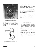
Страница 24: ...9 and move the motor up and remove the V belts off the pulleys Install the new V belts and onto the pulleys and lower the motor to tension the belts When the belts are correctly tensioned tighten the hex nuts and close the motor cabinet MAINTENANCE 1 The unpainted components such as the precision ground cast iron table top should be protected with a coat of paste wax and then buffed dry 2 Regularl...

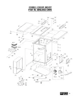
Страница 25: ...25 CX200 CX201 BODY PARTS BREAKDOWN ...

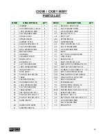
Страница 26: ...5 8 20 3 21 FLAT WASHER 8MM 1 55 MAG SWITCH ASSEMBLY MS 15 1 22 LOCK WASHER 8MM 1 55 1 CONTACTOR CHINT NC1 18 1 23 HEX NOT M8 1 25 1 55 2 OL RELAY CHINT NR2 25 12 18 1 24 DUST HOOD 1 55 3 SWITCH BOX FRONT BACK 1 25 PHLP HD SCR M8 8 8 4 55 4 MAG SWITCH COVER SCREW 1 26 TABLE 1 55 5 ON OF SWITCH CHINT NP2 1 27 EXTENSION WING 2 56 SWITCH BRACKET 1 28 CAP SCREW M8 1 30 6 63 STRAIN RELIEF 1 29 LOCK WAS...

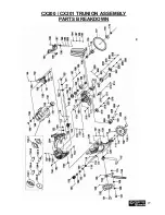
Страница 27: ...27 CX200 CX201 TRUNION ASSEMBLY PARTS BREAKDOWN ...

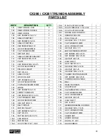
Страница 28: ...ER 1 134 2 MOTOR FAN 1 134 3 R CAP 25M 370V 1 3 4 3 1 134 4 R CAP ACITOR COVER 1 134 5 S CAP 200M 250V 1 1 4 2 3 4 1 134 6 S CAP ACITOR COVER 1 134 7 WIRING JUNCTION BOX 1 135 ORIENTATION PIN 1 136 ROLL PIN 4 28 1 137 HEX BOLT M12 1 75 100 1 138 FLAT WASHER 12MM 2 139 LOCK WASHER 12MM 1 140 HEX NUT M12 1 75 1 141 MOTOR FRAME SUPPORT 1 142 SET SCREW M8 1 25 12 2 143 SET SCREW M8 1 25 30 1 144 HEX N...

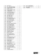
Страница 29: ...03 FLAT WASHER 6MM 2 204 LOCK WASHER 6MM 2 205 CAP SCREW M6 1 25 2 206 SET SCREW M6 1 12 4 207 SPLITTER TIGHTEN CLIP 1 208 LOCK WASHER 6MM 1 209 HEX BOLT M6 1 20 1 210 ORIENTATION BAR 1 211 ROLL PIN 5 25 2 213 LOCK WASHER 5MM 2 214 CAP SCREW M5 8 25 2 215 GEAR 1 216 CAP SCREW M10 1 5 40 1 217 FLAT WASHER 10MM 1 218 LOCK NUT M10 1 5 1 219 GEAR SLEEVE 1 220 PLATE GEAR 1 221 SET SCREW M6 1 20 3 222 H...

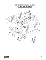
Страница 30: ...30 CX200 CX201 BLADE GAURD PARTS BREAKDOWN ...

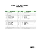
Страница 31: ...PAN HEAD SCREW 1 345 SPACER 2 324 FLAT WASHER 2 346 PAN HEAD SCREW 1 326 TOP GUARD 1 348 FLAT WASHER 10 327 PAN HEAD SCREW 2 349 PAWL 2 328 FRONT GUARD 1 350 SPLITTER 1 331 SIDE GUARD 2 351 RIVING KNIFE 1 332 GUARD CLAMP 1 352 RIVET 1 335 LOCK NUT 3 353 RIVING KNIFE HOOK PLATE 1 336 PAN HEAD SCREW 4 354 HEX BOLT 2 337 ELASTIC PIN 1 355 PAN HEAD SCREW 1 CX200 CX201 BLADE GAURD PARTS LIST ...

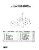
Страница 32: ... 7 6 4 413 CAP SCREW M4 7 14 2 404 CAP SCREW M4 7 14 2 414 POINTER MITER GUAGE 1 405 MITER RING 1 415 FLAT WASHER 4MM 1 406 FLAT HD SCR M5 8 8 1 416 LOCK WASHER 4MM 1 407 MITER BODY PIVOT PIN 1 417 PHLP HD SCR M4 7 8 1 408 MITER GUAGE BODY 1 418 MITER KNOB 1 409 MITER STOP PIN KNOB 1 419 FENDER WASHER 10MM 1 CX200 CX201 MITER GAUGE PARTS BREAKDOWN PARTS LIST ...

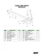
Страница 33: ... HEX BOLT M10 1 5 45 1 505 FENCE SCALE WINDOW 1 515 LOCK NUT M10 1 25 1 506 SET SCREW M12 1 75 15 4 516 CAM FOOT 1 507 PHLP HD SCR M5 8 10 2 517 MAGNET 1 508 LOCK WASHER 5MM 2 518 CAM 1 509 INDICATOR 2 519 FENCE LOCK KNOB 1 510 FENCE BODY 1 520 SET SCREW M12 1 75 30 1 511 SET SCREW 2 521 SPECIAL LOCKING NUT M12 1 75 4 CX200 CX201 FENCE PARTS LIST ...

Страница 34: ...34 CX200 30 RAILS EXTENSION TABLE PARTS BREAKDOWN ...

Страница 35: ... 610 FLAT WASHER 8MM 34 603 SCALE 1 611 REAR RAIL 1 604 FRONT RAIL 1 612 HEX BOLT M8 1 25 40 6 605 CAP SCREW M6 1 16 5 613 HEX NUT M8 1 25 18 606 LOCK WASHER 6MM 13 614 TABLE BOARD 1 607 FLAT WASHER 6MM 13 615 HEX BOLT M8 1 25 30 3 608 HEX BOLT 5 16 18 1 1 2 2 CX200 30 RAILS EXTENSION TABLE PARTS LIST ...

Страница 36: ...36 CX201 50 RAILS EXTENSION TABLE PARTS BREAKDOWN ...
Страница 37: ...0 2 607 FLAT WASHER 6MM 13 618 CAP SCREW M6 1 16 6 608 HEX BOLT 5 16 18 1 1 2 2 619 CAP SCREW M8 1 25 20 4 609 LOCK WASHER 8MM 22 620 HEX BOLT M8 1 25 30 3 610 FLAT WASHER 8MM 34 621 GUIDE TUBE 1 612 HEX BOLT M8 1 25 40 6 622 SCALE 1 613 HEX NUT M8 1 25 18 623 FRONT RAIL 1 614 TABLE BOARD 1 624 REAR RAIL 1 CX201 50 RAILS EXTENSION TABLE PARTS BREAKDOWN ...
Страница 38: ...er handy All returned merchandise will be subject to a minimum charge of 15 for re stocking and handling with the following qualifications Returns must be pre authorized by us in writing We do not accept collect shipments Items returned for warranty purposes must be insured and shipped pre paid to the nearest warehouse Returns must be accompanied with a copy of your original invoice as proof of pu...

Отзывы: