20 • MultiFlex I/O Board Operator’s Guide
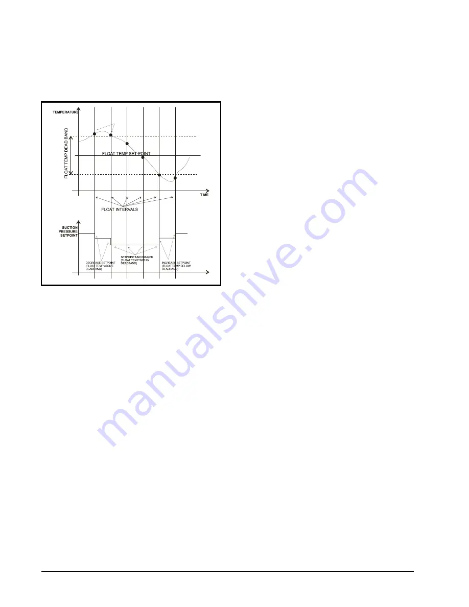
temperature in line with the float setpoint. A
graph showing an example of suction pressure
setpoint adjustment versus float temperature is
provided in
.
The amount of the interval for each adjust-
ment, as well as the frequency of adjustment, is
programmable by the user. Also, the user must
specify a minimum and maximum range for the
suction setpoint to prevent suction float from
floating the setpoint too high or too low.
6.1.5.1.
Suction Float Input Sources
Up to 20 case temperatures may be used to
provide the combined case temperature used
during suction float. The E2 may use case tem-
peratures from:
•
Standard Circuit applications in the E2,
•
Emerson Climate Technologies EC2 case
controllers,
•
Danfoss EKC514 SNMP case controllers,
•
WCC case controller (Microm/Tektronix/
Barker/Elm/CDK),
•
Danfoss DFMC Micro-Cool case controllers.
Each case temperature input value used in
the combination is determined by taking the
average value of the input over a time window
(called the averaging window), which averages
all sampled temperatures between the current
time and
x
minutes before the current time
(where x is the user-defined averaging window
time period). Once the averages of each input are
determined, these values are then combined into
a single temperature by calculating either the
average value, the median value, or the maxi-
mum value. The result, called the
float temper-
ature
, is compared to the float setpoint to
determine which direction to float the suction
pressure setpoint.
6.1.5.2.
Defrost Inhibit
All case temperatures used as inputs for Suc-
tion Float are only used in the combined case
temp calculation if they are in refrigeration
mode. If a case is not in refrigeration mode, its
temperature input value will be ignored.
This includes cases in defrost, pump down,
drip or "drain" mode, clean or "wash" mode, and
cases whose case control devices are offline or
otherwise shut down.
If a case that is being inhibited returns to
refrigeration mode, the E2 will wait for a user-
defined delay period to elapse before including
its temperature value in the combined case temp
calculation. The inhibit delay is designed to
allow the case enough time to recover its case
temperature setpoint.
6.1.5.3.
Bad Case Temp Inhibit
In addition to excluding case temperatures
from circuits or case controllers that are not in
refrigeration, the PAK application in the E2 will
exclude up to a user-defined number of case
temperatures from cases determined to be "poor
performers." A poor-performing case is defined
as one whose temperature deviates outside of the
float temperature deadband.
Figure 6-1
- Suction Pressure Setpoint Vs. Float Temperature
Содержание MultiFlex PAK
Страница 1: ...026 1712 Rev 3 03 JAN 2008 MultiFlex PAK Compressor Condenser Control Board User s Guide...
Страница 2: ......
Страница 4: ......
Страница 8: ......


