


34
INSTALLATION
INSTALLATION MANUAL
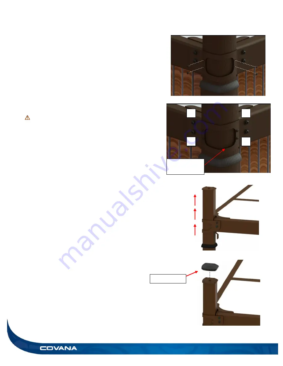
Figure 72
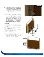
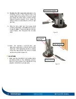
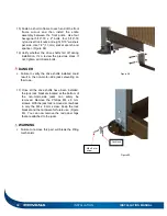
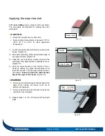
29) Then, use four #8
x 1/2″ self-tapping Robertson
screws to fasten one bracket to its post. (Figure
70) Tighten with care; self-tapping screws can
break when screwed in too hard.
Note:
Follow the pattern shown in Figure 71 (A
to D).
Note:
When screwing in the screws, it is
recommended to pull the post towards you for a
better fit of the corner bracket.
This will
diminish the possible gap.
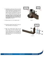
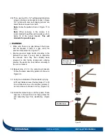
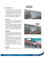
WARNING
Make sure there is no gap between the sleeve
and the bracket. If there is a gap, verify the
previous step (step 29). (Figure 71)
Review previous steps before screwing in the
Roberston screws; it is very hard to reposition
the sleeves once they have already been
screwed in. We highly recommend verifying
whether the posts are level before screwing in
the corner bracket.
30) Repeat step 29 for the remaining brackets.
Follow the same assembly pattern as shown in
Figure 69.
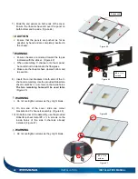
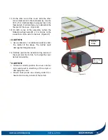
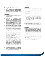
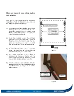
31) Verify the installation of the brackets by trying
to lift each
inner
sleeve. Review steps 27 to 30
for any broken screws or to retighten screws if
an inner sleeve continues to move. (Figure 72)
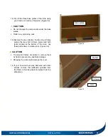
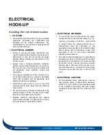
32) Install the rubber caps on all four posts. These
caps are in the part box and help protect the
post assembly tops from weathering. (Figure
73)
Figure 70
A
D
C
B
B
Figure 71
No gap should
be present
Figure 73
Rubber cap
Содержание Evolution GHSC
Страница 1: ...1 INSTALLATION MANUAL Revision 1 2017 05 29 Revision 2 2017 11 10...
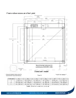
Страница 44: ...44 TECHNICAL SPECIFICATIONS INSTALLATION MANUAL Figure 85 NOT TO SCALE Long side LS model 8 feet only...
Страница 49: ...INSTALLATION MANUAL APPENDIX 49 APPENDIX...
Страница 50: ...50 APPENDIX INSTALLATION MANUAL Wiring diagram North America 60 Hz 120 VAC Operator...
Страница 51: ...INSTALLATION MANUAL APPENDIX 51 Wiring diagram Europe 50 Hz 220 VAC Operator...
Страница 53: ...INSTALLATION MANUAL INSTALLATION CHECKLIST Customer copy 53...
Страница 56: ...56 INSTALLATION MANUAL...


