3
‐
8
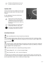
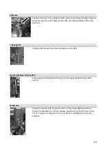
1.
Turn
off
the
shop
circuit
breaker.
2.
Make
sure
the
machine
circuit
breaker
switch
on
the
electrical
compartment
door
is
turned
to
OFF.
3.
Remove
the
screw
securing
the
electrical
compartment
and
then
open
the
door.
4.
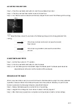
Pull
the
power
supply
cable
and
grounding
conductor
through
the
power
supply
inlet
into
the
electrical
compartment.
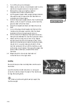
(Shown
right)
5.
Connect
the
power
supply
cable
to
the
circuit
breaker
(N.F.B.)
to
the
R,
S
and
T
terminals,
and
connect
the
ground
cable
to
the
E
terminal.
6.
Close
the
compartment
door
and
fasten
the
screw
back.
7.
Turn
on
the
shop
circuit
breaker
and
then
turn
the
machine
circuit
breaker
switch
to
ON.
The
Power
Indicator
on
the
control
panel
will
come
on.
8.
Pull
to
unlock
the
Emergency
Stop
button
and
press
the
hydraulic
ON
button
to
start
the
hydraulic
motor.
9.
Make
sure
the
sawing
area
is
clear
of
any
objects.
Start
the
blade
and
check
the
blade
rotation.
If
the
electrical
connections
are
made
correctly,
the
blade
should
run
in
a
counterclockwise
direction.
If
not,
shut
the
hydraulics
off,
turn
off
the
machine
as
well
as
the
shop
circuit
breaker.
Then
swap
the
power
the
power
cable
conductors
connected
to
R
and
T
terminals.
10.
Repeat
step
6
to
9
to
ensure
the
electrical
connections
are
in
the
right
order.
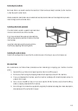
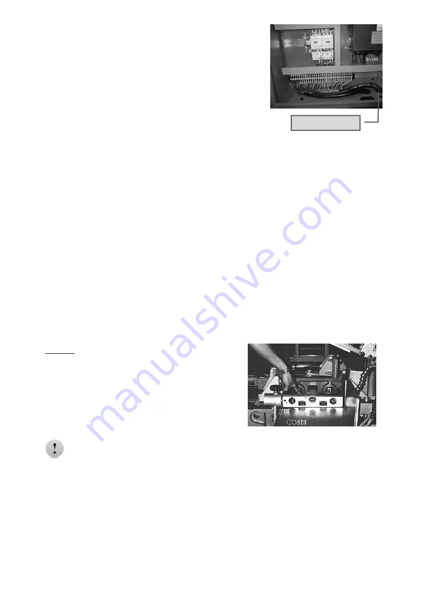
Leveling
Place
spirit
level
on
the
vise
slide
plates
and
the
work
feed
table.
Level
the
machine
in
both
directions
i.e.
along
and
across
the
machine.
Adjust
the
level
of
the
machine
by
turning
the
leveling
bolts.
Make
sure
all
leveling
bolts
evenly
support
the
machine
weight.
Power Supply Inlet
Содержание SH-3026L
Страница 2: ......
Страница 8: ......
Страница 13: ...1 5 Illustration Emergency Stop Emergency Stop Button ...
Страница 15: ...1 7 Illustration Safety Labels ...
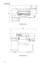
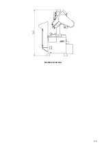
Страница 20: ...2 4 FLOOR PLAN Machine top view Machine front view ...
Страница 21: ...2 5 Machine front view ...
Страница 22: ......
Страница 32: ......
Страница 48: ......
Страница 50: ...5 2 ...
Страница 51: ...5 3 ...
Страница 52: ...5 4 ...
Страница 53: ...5 5 ...
Страница 54: ......
Страница 55: ...6 1 Section 6 HYDRAULIC SYSTEM HYDRAULIC CIRCUIT DIAGRAM ...
Страница 56: ...6 2 ...
Страница 62: ......
Страница 79: ...6 5 4 1 2 3 7 8 9 SH 3026L 2015 12 4 COLUMN ASSEMBLY S3026 11000 立柱組 SERIES PART LIST 10 7 ...
Страница 81: ...1 4 3 2 HEIGHT CONTROL ASSEMBLY SH 3026L 2015 12 8 S3026 11400 高度控制組 SERIES PART LIST 10 9 ...
Страница 83: ...SH 3026L 2015 12 8 CONTROL BOX ASSEMBLY S3026 13000 控制箱組 SERIES PART LIST 5 1 3 4 2 10 11 ...
Страница 85: ...3 2 5 4 1 VISE ASSEMBLY SH 3026L 2015 12 8 S3026 22000 虎鉗組 SERIES PART LIST 10 13 ...
Страница 88: ...SH 3026L 2015 12 10 S3026 30000 鋸弓組 SAW BOW ASSEMBLY SERIES PART LIST 5 13 3 4 8 10 16 ...
Страница 97: ...2015 12 4 SAW ARM ASSEMBLY SH 3026L C260L 31000 鋸臂組 SERIES PART LIST 6 7 9 5 11 10 2 4 8 3 1 10 25 ...
Страница 99: ...2015 12 4 WIRE BRUSH ASSEMBLY SH 3026L C260L 32200 鋼刷組 SERIES PART LIST 4 3 6 5 7 7 9 1 8 2 8 10 27 ...
Страница 101: ...IDLE WHEEL ASSEMBLY SH 1000F 2015 12 4 C300H 30300A 上輪組 SERIES PART LIST 1 6 2 5 3 7 8 6 4 10 29 ...
Страница 104: ......
Страница 105: ......

